
- automatic coop door
- motorised door project
- animal safety
- motor control
- maker projects
Automatic Coop Door: Four Designs That Cannot Trap
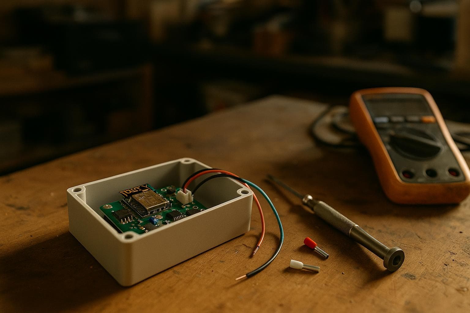
An automatic coop door has one job that matters more than opening at dawn: it must stop before it puts force on a bird. No sensor alone can guarantee that result; a safe design combines a positive drive, measured current limiting, independent end stops, and a manual release that still works with the power off.
Fundamentals and safety circuit
Light sensors and schedules solve timing, not mechanics. A photocell can tell a controller that dusk has arrived, and a real-time clock can command a motor at a repeatable hour, but neither knows whether a chicken is standing in the opening. The door needs a motion system that detects resistance and a physical arrangement that fails without dropping or pinching the panel.
A door driven by a cord and gravity closes uncontrolled if the cord breaks. A positive drive is safer because the motor, screw, rack, or toothed belt remains mechanically connected to the door instead of relying on a cord to restrain its weight. Positive drive does not automatically make a door safe. A broken belt can still release a panel, and a backdriving screw can still let one fall. Test the actual mechanism with power removed and with its fasteners loosened enough to represent a realistic failure.
Set the motor current limit from measurements, not from a guessed percentage. Record current while the finished door runs through its dirtiest, coldest, and least favourable normal conditions. Leave enough margin above that running current to avoid nuisance trips while keeping the limit below the force that could injure an animal. The correct value depends on the motor, gearbox, driver, supply voltage, friction, and door mass.
Current sensing has limits. A soft obstruction may not raise current quickly, and a dirty rail can make the controller interpret normal friction as a bird. Use a reversible drive, short current-trip timing, and a second safety method where the geometry allows it. A compliant leading edge, a slip clutch, or a spring-loaded linkage can limit force, but each introduces another part to test.
Use normally closed end switches where the controller supports that arrangement, so a broken switch wire looks like a fault rather than permission to continue. Put the switches where the door reaches its real mechanical ends, not where a drawing says it should stop. Add a hard stop behind each limit, because firmware should not be the only thing preventing an overrun.
Wire the safety chain to interrupt motor power or the driver enable line, not merely set a variable that the main program might ignore. Use a fuse close to the battery or power supply. A sensible test sequence is:
- Operate the manual release with the door at each end and the controller disconnected.
- Confirm that each end switch stops motion and that a broken switch wire prevents motion.
- Measure normal current at the worst expected friction, then set the closing limit above that value and below the chosen safe force.
- Place a soft test block at several points along the closing edge and verify stop-and-reverse behaviour.
- Remove power during travel and check whether the panel holds, drops, or can be released safely.
- Reconnect power with the door between ends and confirm that startup does not assume a false position.
- Repeat the tests after adding guards, weather seals, paint, or bedding debris.
A door that stops safely but stays closed after a fault is preferable to one that keeps trying. The controller can report a fault with an LED or buzzer, but the fault state must not be cleared by another automatic close command. The manual switch should have a clear open and close position and be accessible without placing a hand in the door path.
1. Vertical lift with a lead screw
This is the project we would pick for a first automatic coop door when the opening is narrow and the panel can travel straight up. It solves the common problem of a door that drifts down after the motor stops. The screw carries the panel rather than a hanging cord, and many screw arrangements resist backdriving better than a free-hanging lift. Do not assume every lead screw is self-locking; pitch, lubrication, load, and wear change that behaviour.
Use a rigid wood or acrylic panel with clearance for swelling, dirt, and ice; vertical guides; a bottom sill that cannot become a sharp pinch point; a geared DC motor or screw actuator; a lead screw, nut, coupling, two end switches, and a current-limited driver. Add a light sensor or real-time clock, fuse, manual reverse switch, power disconnect, and guards over the screw and coupling.
Alignment is the hard part. A screw can lift a panel that feels light by hand while bending its guides when the panel is slightly twisted. Build the guides first, mount the panel, and turn the screw by hand through the full travel. It should not tighten at either side of the opening. Then measure motor current with the door empty, with ordinary dirt on the guides, and with the panel held lightly at several points. A trip limit that works on a clean bench may nuisance-trip at dawn.
The manual override should not be a command buried in software. Fit a power-off release or clutch that lets the panel move by hand without removing the cover. Mark the safe travel ends physically. If a person can lift the panel while the screw remains engaged, check that the motor is not being spun beyond its rated speed.
2. Horizontal rack-and-pinion slider
A horizontal door avoids the falling-panel problem and suits a wall where there is no room above the opening. A broad panel can rest on a sill or rollers while the motor supplies only the force needed to slide it. A rack and pinion is preferable to a cord or smooth friction wheel because the teeth preserve position when the panel is dirty or damp.
Use a sliding panel, two parallel guides or rollers, a rack fixed along the panel, a geared motor, and a guard over the teeth. Add two end switches, a current-limited driver, reverse control, fuse, light sensor or clock, and a manual open-close switch near the door. Provide drainage and a removable debris cover for the lower guide.
The hard part is keeping both sides moving together. A single rack can pull one corner while the other drags. That drag raises current and can trigger a false obstruction stop, or twist the panel until the rack disengages. Keep the guides parallel, provide adjustment at one mounting end, and test the panel with the motor disconnected before adding automation.
On a closing trip, excess current should stop the motor, wait briefly, and reverse far enough to release the obstruction. On an opening trip, the same trip may mean a jam in the opposite direction and should stop without repeatedly forcing the mechanism. Measure the reverse distance so the release motion does not drive the panel into a second obstacle.
This is also the project where the cheap option is often good enough. A simple light sensor and a wired reversing switch can be more reliable than adding Wi-Fi, an app, and remote commands. Remote control fixes a convenience problem, not a trapped-animal problem, and it adds a failure path without improving the local safety circuit.
3. Hinged flap with a crank linkage
A hinged flap works where a vertical or sliding panel would interfere with the wall. The motor rotates a crank, and a connecting rod swings the flap through its arc. It solves the layout problem, but it creates the most complicated pinch zones, so this would not be our first choice for a new opening.
Use a lightweight flap with a protected hinge line, low-voltage geared motor, crank, connecting rod, adjustable clevis, open and closed end switches, current-limited driver, fuse, local manual switch, physical stop, and guarded motor enclosure. Position the switches on the mechanism rather than guessing from time.
The changing geometry of the linkage is the hard part. Near some points in the crank rotation, a small motor movement produces little flap movement but high closing force. Near others, the flap moves quickly with less mechanical advantage. A current limit that seems safe through the middle of the stroke may still allow excessive force near the sill or hinge.
Keep the linkage away from the animal side, and make the closing edge flexible or shielded where possible. Do not place the end switch at the crank's most loaded position if a stalled motor can keep pushing after the switch changes state. Use a normally closed switch for each end, then verify that opening a wire stops motion.
Avoid an over-centre linkage unless you have a specific reason to use one. It can hold a flap shut against wind, but it can also lock the mechanism so the manual release cannot move the door in the expected direction. With the motor disconnected, operate the flap through its full arc and confirm that the release works from both the open and closed positions.
4. Low-power door with a real-time schedule
This project is for a remote run where mains power is unavailable and daylight is not a dependable trigger. It uses a real-time clock and battery-backed controller, while a small geared motor moves a lightweight positive-drive door. A light sensor can serve as a secondary condition, such as refusing to close if the light level suggests unusual activity.
Use a lightweight panel, low-friction guides, a geared DC motor or screw actuator chosen for the lowest practical running current, a battery, suitable charge controller, protected solar input if used, real-time clock, low-power microcontroller, end switches, current sensing, fuse, manual open-close switch, and power-off mechanical release.
The hard part is the low-voltage condition when the door needs to close. Battery voltage falls under motor load, especially in cold conditions, and a controller can brown out halfway through travel. Measure voltage at the motor terminals while the door starts, runs, and stalls against a safe test fixture. Add a rule that refuses to begin a cycle below the measured safe voltage, then leaves the door in a known state rather than retrying forever.
A schedule also needs a recovery policy. If the clock resets, the light sensor fails, or the controller reboots during travel, the motor should remain off until an end switch or supervised manual command establishes the door position. Store the last known direction only if the hardware can verify it; a software flag is not proof that the panel is open.
This is the project where we would not buy the upgrade yet. Remote notifications, a camera, and cloud control are useful only after the local mechanism has passed power-loss, obstruction, and switch-failure tests. A plain clock, local switches, and a fuse are enough for the first working version.
A current limit is not enough to prevent a chicken from being trapped. It depends on motor speed, friction, gearbox ratio, driver behaviour, and reaction time, while a soft or light obstruction may not produce a large current rise. Combine current limiting with reversible motion, guarded edges, end switches, hard stops, and a tested manual release.
Use a schedule when opening time must be repeatable, and use a light sensor when local daylight should decide. Our preferred arrangement is a schedule with a light-level sanity check and a local manual switch. Neither input should restart a door that stopped on an obstruction.
We build automatic coop doors to order through Custom Electronics & Smart Systems and Custom Woodworking; request a quote.
Related services
All services →
Have a project in mind?
Tell us what you want built — we reply within 24–48 hours.