
- i2c
- arduino
- sensors
- electronics
- debugging
I2C Scanner: Ten Lines That Save an Afternoon
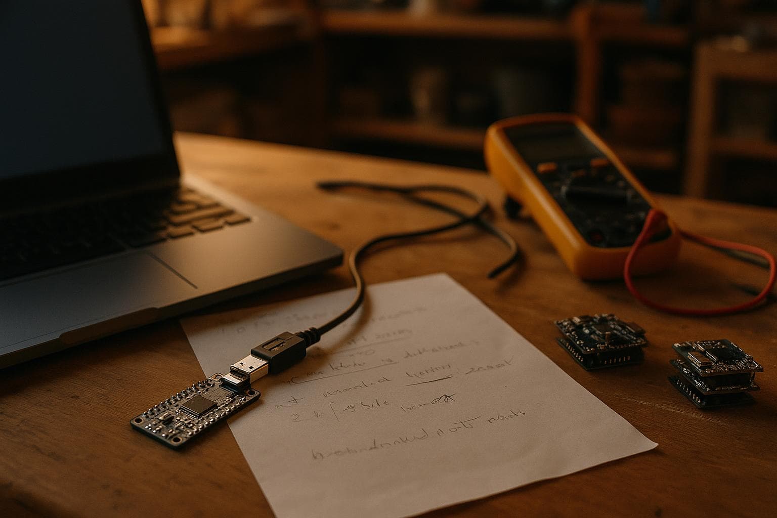
A sensor that is not detected does not automatically need a new library, a different board, or a longer sketch. The fastest first test is an I2C scanner: ten lines that ask every valid 7-bit address for an acknowledgment before any device driver is involved.
That order matters. A scan that finds nothing points first at wiring, power, or missing pull-ups. A scan that reports every address points strongly to a data line stuck low. Both results tell you what to inspect before you spend an afternoon debugging code that has not had a chance to run.
Build the I2C scanner before the sensor code
For an Arduino-compatible board using the standard Wire library, this is enough to make the first test:
#include <Wire.h> void setup() { Serial.begin(115200); Wire.begin(); for (byte address = 1; address < 127; address++) { Wire.beginTransmission(address); byte error = Wire.endTransmission(); if (error == 0) { Serial.print("0x"); if (address < 16) Serial.print("0"); Serial.println(address, HEX); } } } void loop() {}
This scans the usable 7-bit address range from 0x01 through 0x7E. It reports an address when Wire.endTransmission() returns zero, meaning the device acknowledged the address phase. It does not identify the part, prove that a register can be read, or validate a driver.
Some boards use different I2C pins, especially boards with multiple hardware buses. On those, Wire.begin() may select the correct pins automatically, or it may require explicit SDA and SCL pin arguments. Check the board's pin definition rather than assuming the pins marked A4 and A5 apply to every controller.
The first stage normally takes 30 to 60 minutes. If the board is already on hand, the extra cost is roughly $0 to $5 for jumpers or a small breadboard. If not, a basic microcontroller board and breadboard setup is often roughly $10 to $30. Do not buy a logic analyzer yet. It fixes a measurement problem, not an unverified wiring problem.
Open the serial monitor at the baud rate used in the sketch. Record the result before changing wires. A repeatable result is more useful than a scan performed once between several changes.
Read the scan as an electrical test
The output is a branching decision, not a parts finder. Use the result to choose the next check.
| Scan result | Likely bus condition | First checks | What it points to |
|---|---|---|---|
| No addresses | SDA and SCL are not producing a valid acknowledgment | Power, ground, SDA, SCL, pull-ups, pin selection | Wiring, power, missing pull-ups, wrong voltage, or an unpowered device |
| One expected address | One device is answering normally | Confirm its address and supply voltage | The bus is probably sound; move to register-level testing |
| Two or more expected addresses | Multiple devices are present | Compare the list with each device's address options | Normal operation, unless two parts share one fixed address |
| Every address from the scan responds | SDA is commonly stuck low or the bus is electrically misread | Disconnect devices, inspect SDA for a short, check pull-ups and voltage levels | A data-line fault, not a missing driver library |
| The board hangs during the scan | SCL or SDA may be held low, or the controller is waiting on a bus state | Remove peripherals, check for a short, add a bus timeout if supported | A locked bus or board-specific Wire behavior |
No devices is the result beginners most often misread. It does not prove the sensor is defective, and it does not point first at the driver library. Check the sensor's supply voltage, shared ground, SDA and SCL order, and whether the breakout includes pull-up resistors.
I2C lines are open-drain signals. Devices pull a line low and release it; resistors pull the line back high. Some controller boards and sensor breakouts include pull-ups, but the I2C specification does not make them magically appear in a loose-wire setup. Missing pull-ups can produce no addresses or unreliable results. Too many parallel pull-ups can also make the bus pull too hard, especially as more boards are added.
Every address appearing to respond is a different clue. It is the signature of SDA stuck low because the controller sees the data line held in the acknowledgment state. A solder bridge, damaged breakout, wrong level shifter connection, or a pull-down on SDA can cause it. Disconnect all peripherals and scan the controller alone. If every address still appears, inspect the controller-side SDA path. If the result clears when one board is removed, that board or its wiring deserves attention.
A scan that reports one expected address is not the end of the test. It proves that the address phase works. It does not prove that the sensor is in the correct operating mode or that the requested register format is correct.
Prove the bus with one known device
The second stage is a minimal read from one device whose address and register map are documented. Use a sensor with a fixed or clearly selectable address, and connect no other I2C devices. This stage usually takes one to two hours. The added cost is roughly $5 to $20 for a basic sensor breakout if the scanner hardware is already assembled.
Before using the manufacturer's example, write down four facts:
- The supply range for the exact sensor variant.
- The controller pins assigned to SDA and SCL.
- The device's 7-bit address, not an address shifted left for a low-level transaction.
- The register address, read length, and required delay or conversion command.
Address notation causes a large share of false leads. A datasheet may show an 8-bit write value and an 8-bit read value, while the scanner prints the 7-bit address. For example, a scanner result of 0x68 corresponds to a transaction address byte of 0xD0 for writing and 0xD1 for reading. That conversion is part of the protocol, not a change to the sensor's address.
Read a fixed identity register if the part provides one. A changing measurement is a poor first proof because it can look plausible even when scaling, byte order, or initialization is wrong. If the identity value is correct, then test one measurement and compare its behavior against the datasheet's expected range.
If the scanner sees the device but the identity read fails, move to register details. Check whether the register pointer must be written before the read, whether a repeated start is required, and whether the device needs a wake command. At this point a driver library can be useful, because the electrical path has already passed a meaningful test.
Add the driver only after the scan passes
The third stage is adapting the driver library. Set aside two to four hours for a common sensor and longer if the library targets a different controller family or assumes a different bus API. The cost is usually $0 because the software is available from the board or sensor project, though a second sensor or level shifter may add roughly $5 to $20.
Start with the library's smallest example. Change one thing at a time:
- Set the correct SDA and SCL pins if the board requires it.
- Set the detected 7-bit address if the library exposes an address parameter.
- Confirm that the initialization call returns success before reading values.
- Print raw register bytes before applying conversion formulas.
- Add a short delay only where the datasheet requires conversion time.
If the scan finds the expected address but the library says sensor not detected, the likely problem has moved from basic wiring to software assumptions. Common causes include a different address strap, a chip variant with another identity register, an unsupported bus object, or an initialization sequence that does not match the part.
Do not replace the driver first. Put a raw register read beside the driver and compare the results. If the raw read works, inspect the library's address handling and identity check. If the raw read fails, return to the datasheet and bus transaction rather than adding unrelated code.
A cheap logic analyzer becomes useful here, not earlier, when the scanner and a raw read disagree. It can show whether the controller sends the expected address, whether the device acknowledges, and whether SDA changes while SCL is high. Budget roughly $10 to $40 for a basic analyzer, and allow another hour to capture and interpret a transaction. That purchase is worthwhile only if the disagreement cannot be reduced with a meter and a known-good wiring setup.
Finish with a repeatable test fixture
Once one sensor reads correctly, add the second device and rescan. This stage often takes one to three hours. The added hardware cost depends on the second device, but roughly $5 to $25 covers many small sensor boards and a few resistors. Keep the first working arrangement intact so each new connection has a known comparison.
Check address conflicts before writing application logic. Two devices with the same fixed address cannot share one bus without changing an address pin, using a bus switch, or placing one device on another controller bus. A successful scan of both addresses does not guarantee that their voltage levels are compatible, either. A 5 V controller and a 3.3 V peripheral need a suitable electrical interface unless the board documentation explicitly supports the connection.
For a permanent fixture, measure the idle voltage on SDA and SCL with a meter. Both lines should rise toward the bus pull-up voltage when no device is pulling them low. A line that remains near ground is not a driver-library problem. A line that rises slowly may indicate excessive capacitance, too many pull-ups in parallel, long wiring, or a bus speed that is too high for the layout.
Only after the multi-device scan, raw reads, and address checks pass should the bus become part of the larger project. The scanner then remains useful as a service test: run it before changing application code, and compare its address list after every wiring change.
Frequently asked questions
Why does my I2C scanner find nothing?
Start with power, shared ground, SDA, SCL, the selected controller pins, and pull-ups. A scan that finds nothing points at wiring, power, or missing pull-ups rather than at the driver library. Also verify that the breakout is enabled and that its voltage is within the exact part's supply range.
Why does every I2C address respond?
Every address appearing to respond is the signature of SDA stuck low. Disconnect the peripherals and scan again, then inspect SDA for a solder bridge, damaged level shifter, wrong connection, or an unintended pull-down. If the bus hangs instead, SCL may be held low or the controller may be waiting on a locked bus.
Does a detected address prove the sensor works?
No. It proves only that something acknowledged the address phase. A raw identity-register read is the next useful test, followed by one documented measurement and then the driver library.
We build I2C sensor and controller projects to order through custom electronics and smart systems.
Related services
All services →
Have a project in mind?
Tell us what you want built — we reply within 24–48 hours.