
- learning electronics
- project progression
- electronics projects
- datasheets
- circuit testing
Learning Electronics: 6 Projects That Build Skill
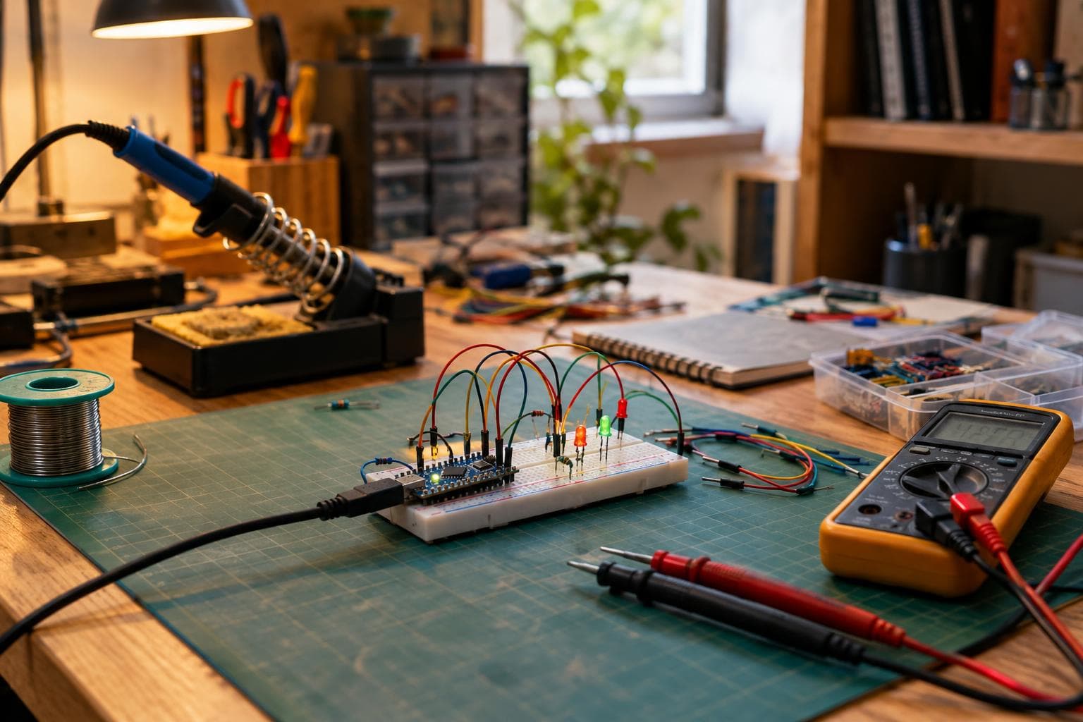
The fastest way to improve at electronics is not collecting more kits. It is finishing circuits that force a decision, measuring what happened, and changing the design based on evidence.
A finished imperfect project teaches more than a perfect plan that is never built. The sequence below moves from current-limited power to switching, timing, sensing, and firmware. Each project solves a practical problem, and each has one part that tends to be harder than its schematic suggests.
Build a project progression instead of a parts pile
Use the same loop on every build: predict, assemble, measure, compare, then revise. Write down the expected voltage, current, timing, or sensor value before probing the circuit. A measurement that disagrees with your prediction is useful data, not an interruption.
Read the datasheet before choosing a part. Look for absolute maximum ratings, recommended operating conditions, pin functions, input thresholds, output-current limits, timing diagrams, and the test conditions behind electrical specifications. A part number is not a design rule. Two variants in the same family can have different pin functions or voltage limits.
For learning electronics, start with circuits where a wrong assumption is easy to see and hard to hide. I would rather see a beginner build six plain projects with test points than buy a development board loaded with features that never get measured.
The table gives the progression in technical terms. The current figures are working targets or questions to answer, not universal settings.
| Build | Supply or signal range | Main measurement | Tolerance that matters | Common failure mode |
|---|---|---|---|---|
| LED indicator | Low-voltage DC; set LED current from the LED data | Voltage across LED and resistor | LED forward voltage varies by colour and current | LED wired backward or resistor omitted |
| Transistor switch | Logic signal plus a separate load supply | Base or gate voltage and load current | Logic threshold must match the transistor variant | Load current exceeds the switching path |
| Bench power monitor | Regulated DC rail within the regulator limits | Input, output, ripple, and heat | Resistor and divider tolerances affect readings | Grounding or polarity error |
| Timer and buzzer | Timer supply within the IC data sheet limits | Frequency and duty cycle | Capacitor tolerance shifts timing | Timing node is loaded by the next stage |
| Sensor logger | Sensor voltage or digital bus plus MCU supply | Raw reading and reference voltage | Sensor accuracy and ADC reference stability | Firmware assumes ideal units or range |
| Light-controlled actuator | Sensor, controller, driver, and motor or relay supply | Threshold, startup current, and noise | Driver rating must exceed the real load | Switching noise resets the controller |
Projects 1 to 3: make current and voltage visible
1. A protected LED status indicator
Problem it solves: You need a clear power or state indication without damaging the LED or the controller pin driving it.
Main parts and materials: One LED, one series resistor, a low-voltage DC source, a breadboard or terminal strip, hookup wire, and a multimeter. Add a pushbutton if you want the LED to show an input state.
Harder than it looks: Choosing the resistor from the real LED forward voltage and desired current, rather than copying a colour-coded value from a tutorial.
For a simple series circuit, start with the resistor equation:
R = (V_supply - V_LED) / I_LED
The LED forward voltage depends on colour, current, temperature, and the specific part. Use the data sheet's forward-voltage curve or test at a conservative current. A starting target around 5 to 15 mA is reasonable for many indicator LEDs, but the LED data sheet and the output pin limit decide the permitted value.
Measure the voltage across the LED and the resistor separately. If the resistor voltage is nearly the full supply voltage, the LED may be reversed, open, or damaged. If the LED is bright but the measured current is much higher than expected, stop and correct it before connecting a microcontroller pin.
This project is intentionally cheap. Do not buy a bench power supply for it if a known, regulated low-voltage source and a multimeter are already available. The upgrade fixes a problem you do not have yet.
2. A transistor-controlled load switch
Problem it solves: A small logic signal needs to control a load that draws more current than a microcontroller pin should provide.
Main parts and materials: A logic-level N-channel MOSFET or an NPN transistor selected from its data sheet, a resistor for the control input, a load such as an LED strip segment or small DC fan, a flyback diode for an inductive load, and separate supply wiring for the load.
Harder than it looks: Confirming that the transistor is actually suitable at your gate or base voltage. “Logic-level” is not a sufficient specification by itself.
For a MOSFET, read the on-resistance rating at the gate-source voltage you will actually use. A value listed at 10 V does not prove that the part switches efficiently at 3.3 V. For an NPN transistor, calculate base current and check the forced gain assumption used for saturation. In both cases, verify the package pinout for the exact variant.
Measure the control voltage, the voltage across the switching device while on, and the load current. A hot transistor or a weakly running load means the switching path has too much resistance, the load supply is wrong, or the device is outside its intended conditions. Add the flyback diode across a relay coil, solenoid, or brushed motor, with its cathode toward the positive supply. The diode protects the switch from the inductive voltage spike when current is interrupted.
Keep the grounds connected at the correct reference point, but keep high load current out of thin breadboard jumpers where possible. Startup current can be higher than running current.
3. A small regulated power and load monitor
Problem it solves: You need to know whether a circuit is receiving the voltage and current you think it is receiving.
Main parts and materials: A low-voltage DC source, a regulator module or regulator IC used within its data-sheet conditions, input and output capacitors of the specified type and value, a resistive load, a fuse or resettable protection device, and test points.
Harder than it looks: Separating voltage regulation from power dissipation. A linear regulator drops excess voltage as heat, so its temperature depends on the voltage difference and load current.
Calculate approximate regulator dissipation as:
P = (V_in - V_out) × I_load
Then compare the result with the regulator package, board copper, and permitted junction temperature. A module may include protection, but its rating still depends on airflow, input voltage, and temperature. Read the regulator's required capacitance and stability conditions.
Measure input voltage at the regulator pins, output voltage at the load, and current in series with the load. Long thin leads can create a voltage drop that makes the regulator output look correct at one point and wrong at another. Add a second load and watch whether the output changes. Record the regulator temperature after the circuit reaches a steady condition.
A basic multimeter earns its place here. An oscilloscope is useful later, but it is not required for the first three builds. Buy the measuring tool that answers today's question.
Projects 4 to 6: make time, data, and noise behave
4. A hardware timer with an adjustable buzzer
Problem it solves: You need a repeatable time interval or tone without relying on a computer or a full microcontroller program.
Main parts and materials: A timer IC such as a 555 variant, resistors, a timing capacitor, a potentiometer, a piezo buzzer or small speaker suited to the driver output, a decoupling capacitor, and a switch.
Harder than it looks: The timing capacitor and the next circuit stage interact. Nominal resistor and capacitor values predict a frequency, but tolerance, leakage, supply voltage, and measurement method move the result.
Choose the timer variant first. Bipolar and CMOS 555 devices differ in supply-current behaviour, output drive, input current, and permitted voltage range. Use the exact data sheet for the part in hand. Keep the timing node short, add the recommended supply bypass capacitor close to the IC, and avoid connecting a low-resistance load directly to a timing pin.
Measure the period at the output with an oscilloscope or frequency counter if available. With only a multimeter, you may verify average voltage but not waveform shape or duty cycle. Change one component at a time and record the result. If the frequency changes when you touch the timing node, it is high impedance and picking up interference.
A microcontroller can make the same buzzer project easier to adjust, but the timer circuit exposes thresholds, charge curves, and loading in a way that firmware can hide.
5. A temperature or light data logger
Problem it solves: You need a record of a changing physical condition instead of a single reading taken by hand.
Main parts and materials: A microcontroller board, a temperature sensor or photoresistor circuit, a known reference or supply measurement, a storage method such as serial output or a memory card, a pushbutton for starting a sample run, and a stable enclosure or mounting point.
Harder than it looks: Turning an ADC number into a defensible physical value. The raw count is not automatically volts, degrees, or useful light level.
Start by logging raw readings with timestamps. Measure the sensor supply and the voltage at the analog input with a multimeter. Check the microcontroller data sheet for ADC reference behaviour, input range, resolution, and restrictions on source impedance. If the board uses a supply-derived reference, changes in that supply can look like sensor changes.
Calibrate against known points where practical. For a photoresistor, report relative brightness unless you have a calibration method for illuminance. For a temperature sensor, compare it with a reference under the same conditions and allow both to settle. Sample at a rate that matches the thing being measured; fast sampling cannot repair a slowly responding sensor or mounting arrangement.
Do not smooth every reading before you understand the noise. Save both the raw value and the processed value. A moving average can make a graph pleasant while hiding a loose connection or a short burst of electrical interference.
6. A light-controlled actuator with a safe threshold
Problem it solves: A measured condition should trigger a real action, such as turning on a low-voltage lamp or moving a small actuator, without rapid chatter or controller resets.
Main parts and materials: The sensor logger parts, a transistor or MOSFET driver, a suitable low-voltage load, a flyback diode if the load is inductive, a separate load supply where required, a status LED, and firmware with hysteresis and a timeout.
Harder than it looks: Managing the difference between a clean threshold in code and a noisy physical system.
Set two thresholds instead of one. The actuator can turn on below the lower threshold and remain on until the reading rises above the upper threshold. That gap is hysteresis. Choose it from measured noise and the response of the system, not from a random constant. Add a minimum on or off time if the load needs time to start or stop.
Measure the sensor value, controller supply, load current, and controller supply during switching. A motor or relay can pull the supply down or inject noise through shared wiring. Keep the load return current out of the controller's sensitive ground path, add local decoupling, and verify the driver temperature under the real load. A reset at activation is evidence of a power or layout problem until measurement shows otherwise.
For a first actuator, I would pick a low-voltage load rather than mains switching. It leaves fewer safety variables and makes fault-finding more direct. A relay module can help with a quick prototype, but building the driver once teaches more about the current path.
The two habits that keep project progression moving
Datasheet reading and measurement reinforce each other. The data sheet tells you what a part is allowed to do and under which test conditions. Your meter or scope tells you whether your circuit is operating under those conditions.
Before powering a new build, check:
- polarity, continuity, and the resistance between each supply rail and ground
- the exact pinout and package variant of every active part
- expected voltage at each test point
- expected current through the load and supply path
- whether startup current is different from running current
- whether the measurement instrument changes the circuit
- the temperature of regulators, transistors, resistors, and connectors after a sustained run
Measure at the component pins first, then at the source and load. If the readings differ, the wiring resistance or ground arrangement is part of the circuit. Do not replace a surprising measurement with an assumption that the board must be wrong.
Keep a short build record: part number, supply voltage, measured current, firmware version, changes made, and the failure that prompted each change. That record turns a failed project into a reference design for the next one.
Frequently asked questions
Should I start with Arduino projects or circuits without a microcontroller?
Start with one of each. A bare LED, transistor switch, and timer expose electrical behaviour directly. A microcontroller data logger then adds software, timing, and calibration. Starting with firmware alone can hide a bad power rail or an incorrect input threshold.
How do I know whether a measurement is trustworthy?
Repeat it, change the measuring point, and compare it with a second method where possible. Check the meter range, lead resistance, reference ground, instrument input impedance, and whether the circuit changes when the probe is attached. A plausible value is not proof.
When should I buy an oscilloscope?
Buy one when your question involves waveform shape, frequency, ripple, timing, or a fault that a multimeter cannot resolve. For the first LED, transistor, and regulated-load projects, a reliable multimeter is the better purchase. Use the cheapest tool that can answer the question in front of you.
The Boss Factory builds made-to-order custom electronics, smart systems, and software projects; request a quote.
Related services
All services →Have a project in mind?
Tell us what you want built — we reply within 24–48 hours.