
- energy monitoring
- current transformer
- sct-013
- raspberry pi pico
- electronics
- mains safety
CT Clamp Energy Monitor: SCT-013 Build Guide
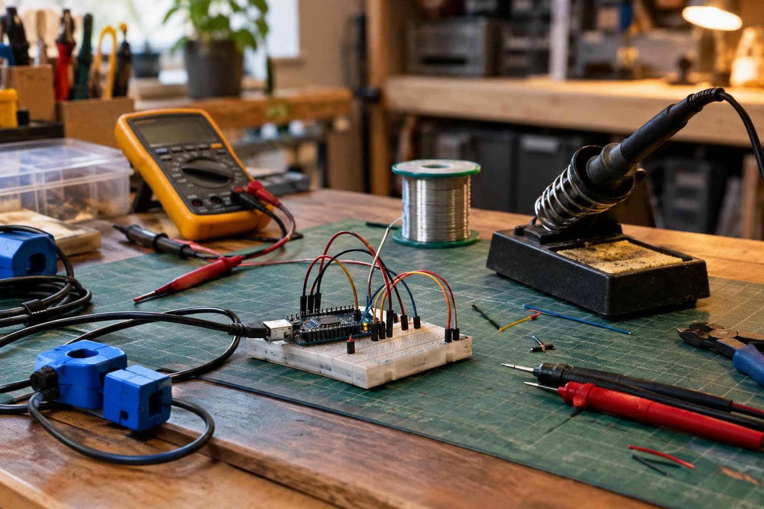
A clamp-on CT can measure the current in a live circuit without putting a resistor in series with the load. The short answer is that an SCT-013 and a correctly sized burden resistor make a useful current channel, but the CT alone does not measure DC or true energy.
Choose the CT and define the measurement
For this build, use an SCT-013-000 rated at 100 A primary and 50 mA RMS secondary. The -000 version has a current-output secondary, so it requires an external burden resistor. Other SCT-013 variants, such as voltage-output versions with an internal burden, need a different calculation and must not be treated as interchangeable.
Use a Raspberry Pi Pico as the sample controller, powered from a regulated 3.3 V USB supply. Its RP2040 ADC accepts a 0 to 3.3 V input, so the alternating signal cannot be connected directly to an ADC pin. The CT output swings above and below zero, while the ADC can only read positive voltage. We will shift that waveform to a 1.65 V mid-rail.
The CT only responds to alternating current. It cannot measure a DC load, such as a battery heater or a DC motor supplied from a battery. A rectifier or software calculation does not fix that limitation; the transformer needs changing magnetic flux.
The clamp must surround one current-carrying conductor. If it surrounds both line and neutral conductors together, their magnetic fields usually cancel and the reading approaches zero. On a split cable, separate the conductors only inside a suitable enclosure or access point, with the mains conductors remaining insulated and mechanically secured.
The secondary ratio gives the first fixed calculation:
- Primary current at the rated point: 100 A RMS
- Secondary current at that point: 50 mA RMS
- Secondary current ratio: 100 A / 0.05 A = 2000:1
- ADC supply: 3.3 V
- Bias target: 1.65 V
Do not design around the rating alone. A 100 A clamp may be used on a circuit that normally draws 8 A, and a burden chosen for full-scale headroom will produce a smaller signal at that normal load.
Fit the burden resistor before connecting the CT
The burden resistor converts the CT's secondary current into a voltage. Fit an 18 ohm, 1% metal-film resistor—roughly 18 ohms nominal—directly across the CT secondary terminals. At 50 mA RMS, the nominal burden voltage is:
0.05 A × 18 ohm = 0.90 V RMS
The sine-wave peak is about 1.27 V. With a 1.65 V bias, the ADC signal should therefore range from roughly 0.38 V to 2.92 V at the CT's rated current, leaving useful space below both 0 V and 3.3 V.
The burden is not an optional measurement accessory. A current transformer with an unloaded secondary can develop a dangerous voltage, even when the primary current is modest. Keep the burden resistor permanently fitted across the secondary, including during installation, testing, and unplugged-controller conditions. Never open-circuit the CT secondary while the clamp is around a live conductor.
The 18 ohm value is a deliberate choice for this 3.3 V ADC and this 100 A to 50 mA CT. The comparison below shows why a larger resistor is not automatically better.
| Burden resistor | Secondary voltage at 100 A RMS | Approximate waveform peak | Result on a 3.3 V ADC biased at 1.65 V |
|---|---|---|---|
| 18 ohm | 0.90 V RMS | 1.27 V | Fits with useful rail margin |
| 33 ohm | 1.65 V RMS | 2.33 V | Clips at both ADC rails |
| 47 ohm | 2.35 V RMS | 3.32 V | Severe clipping and excessive voltage |
If your CT has a different ratio, calculate the burden from the manufacturer's secondary current at the maximum primary current. For a centered sine wave, the approximate upper limit is R = VADC / (2 × sqrt(2) × Isecondary), and the practical value should be lower to allow for supply variation, waveform distortion, and transient current.
Use a resistor with a voltage and power rating suitable for the CT. The nominal burden dissipation here is 0.05² × 18, or 45 mW at the rated current, but a 0.25 W resistor gives useful thermal margin. A 1% part typically reduces calibration error. Do not substitute a trimmer as the permanent burden; its wiper can fail open.
Build the mid-rail ADC input
Make the bias from two resistors, typically 10 kΩ and 1% each, in series between 3.3 V and ground. Their junction is nominally 1.65 V. Add a 10 µF electrolytic capacitor and a 100 nF ceramic capacitor from that junction to ground. The capacitors hold the midpoint quiet while the ADC samples.
Connect the CT secondary and burden as an isolated two-wire signal. Feed one burden terminal through a 1 kΩ resistor to GP26, the Pico ADC0 input. Connect the other burden terminal to the 1.65 V bias node. This puts the CT's AC voltage on top of the bias without connecting the sensing circuit to mains potential. Add a 100 nF capacitor from GP26 to the bias node if the wiring is short and the waveform remains clean; with the 1 kΩ series resistor, it forms a low-pass corner near 1.6 kHz.
A practical connection list is:
- SCT-013-000 secondary terminal A to the 1.65 V bias node
- SCT-013-000 secondary terminal B to the 18 ohm burden and then to the 1 kΩ ADC series resistor
- 18 ohm burden directly between the two CT secondary terminals
- 1 kΩ resistor output to Raspberry Pi Pico GP26, ADC0
- Bias divider midpoint to the Pico ADC ground reference through the circuit ground arrangement
- 3.3 V and ground from the Pico supply to the bias divider
- 100 nF bypass capacitor between Pico 3.3 V and ground close to the board
The burden and bias components belong on a small soldered board or PCB, not on a loose breadboard beside exposed mains wiring. Keep the CT secondary pair twisted, keep the ADC lead short, and separate the low-voltage board from the mains enclosure with a suitable insulating barrier. A USB supply does not make an incorrectly enclosed mains installation safe.
Before clamping onto a conductor, power the Pico and measure the ADC input with a multimeter. With no CT current, expect a DC reading near 1.65 V. The exact reading may differ because resistor tolerance, ADC input behavior, and supply voltage all contribute. If the input sits near 0 V or 3.3 V, stop there. The bias network is not connected correctly, or the ADC pin is not the pin you selected.
Switch off the circuit where the installation method permits it, open the split core, place it around one insulated line conductor, and close the core until its mating faces are fully seated. Do not clamp around a complete two-wire flex, and do not force the hinge against a cable that is too large for the CT opening.
The low-voltage plug and cable still need strain relief. A partially inserted CT plug can leave the secondary open, which is unsafe while the primary carries current. Fit the plug before energizing the monitored circuit, and leave the burden connected even if the Pico is removed.
The CT provides isolation in normal use, but isolation is not permission to route its wiring through a mains compartment without regard to spacing. Keep the low-voltage conductors protected from abrasion and ensure the enclosure, terminals, and supply are rated for the installation. If the circuit is part of fixed building wiring, work within the rules that apply to that installation and use a qualified electrician where required.
The first live test should use a known, steady load. A resistive heater is easier to validate than a refrigerator, dimmer, switched-mode supply, or motor because those loads distort the waveform and can have a poor power factor.
Sample, calculate, and calibrate current
Sample the biased ADC at a fixed rate of at least 2 kHz for a 50 or 60 Hz circuit. A block containing an integer number of mains cycles makes the RMS calculation less sensitive to phase at the start and end of the block. For 50 Hz, 400 samples at 2 kHz covers four cycles; for 60 Hz, 400 samples covers five cycles.
First estimate the bias from the sample block, or use the measured no-load midpoint. For each sample, subtract that midpoint, convert ADC counts to volts, and calculate RMS:
Isecondary_RMS = Vburden_RMS / 18 ohm
Iprimary_RMS = Isecondary_RMS × 2000
The ratio of 2000 applies to the SCT-013-000 specification used here. It does not apply to every SCT-013 model.
A better field calibration uses a clamp meter or a known resistive load. Record the monitor's raw RMS result and the reference current, then apply a correction factor in firmware. Do this near the current range that matters. CT accuracy, resistor tolerance, ADC gain, conductor position in the core, and waveform shape all affect the result. A single-point correction does not guarantee accuracy across the entire range.
For a load that is close to resistive, estimated real power can be calculated as P ≈ Vrms × Irms, then integrated over time for watt-hours. That approximation is not true energy measurement for motors, switch-mode power supplies, dimmers, or other loads with phase shift or harmonic current. A current-only CT channel measures current. A true whole-circuit energy meter also needs a voltage reference, phase relationship, and suitable isolated voltage measurement.
If the monitor is intended to report energy rather than current, add voltage sampling designed for the supply system, or take a verified energy value from a meter that already measures both quantities. Do not connect a mains voltage divider to the Pico ADC as a casual extension of this circuit.
A zero reading usually means the clamp surrounds both conductors, the core is not closed, the CT plug is not seated, or the firmware is subtracting the wrong midpoint. A permanently high reading usually means the bias is missing, the ADC input is saturated, or the burden is not connected as drawn.
A reading that is exactly half or double the expected value points first to the CT ratio, unit conversion, or calibration constant. A reading that changes when the cable moves in the aperture points to conductor position or core closure. A noisy reading with no load points to a long unshielded ADC lead, a weak bias node, a floating secondary, or a power supply injecting noise.
Check these in order:
- Confirm the exact CT suffix and its stated secondary current.
- Measure 1.65 V at the bias node before connecting the CT.
- Verify the 18 ohm burden is physically across the secondary.
- Confirm the clamp surrounds one conductor only.
- Check that the no-load ADC samples center around the measured bias.
- Inspect the raw waveform for clipping before applying RMS math.
- Compare against a steady resistive load before testing motors or electronic power supplies.
Do not buy a higher-resolution ADC as the first response to a bad reading. The wiring, burden, bias, and conductor placement cause more failures in this build than nominal ADC resolution. An external ADC can help after the signal is correctly scaled, but it cannot repair an open secondary, a clipped waveform, or a clamp around both conductors.
Frequently asked questions
Can an SCT-013 measure a battery-powered DC load?
No. A current transformer responds to alternating magnetic flux and does not provide a useful steady-state reading for DC. Use a Hall-effect sensor or a suitably rated shunt arrangement for DC current.
Why does the CT need a burden resistor if the ADC already has an input resistance?
The ADC input is not a defined, safe measurement burden for the CT. The external resistor sets the secondary voltage, controls the signal scale, and keeps the secondary closed if the controller is disconnected. Without it, the CT secondary can develop a dangerous voltage.
Can this circuit report exact kWh from current alone?
No. It can estimate apparent power from current and an assumed voltage, or estimate real power for a known resistive load. Accurate real energy requires voltage, current, phase, and waveform information, or a meter that measures those quantities together.
We build made-to-order custom electronics and smart home systems for projects like this through /quote.
Related services
All services →Have a project in mind?
Tell us what you want built — we reply within 24–48 hours.