
- esp32
- 5v logic
- level shifting
- gpio protection
- electronics
5V Tolerant ESP32? Check the GPIO First
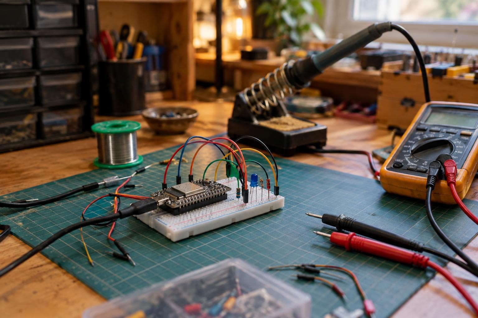
A 5 V sensor, module, or Arduino output can appear to work perfectly on a 3.3 V board. That does not prove the input is safe. The honest answer is that a GPIO is 5 V tolerant only when its datasheet or board schematic says so; otherwise, limit the pin voltage or shift the logic level.
What happens when 5 V reaches a 3.3 V GPIO
On a typical 3.3 V microcontroller input, the protection structure includes a diode from the input toward the supply rail. If the input rises above the chip's supply voltage by roughly a diode drop, that diode conducts. Driving 5 V into a 3.3 V input therefore forces current through the chip's internal protection diode into the supply rail.
That current has somewhere to go. It may raise the local 3.3 V rail, feed other circuits through the supply, disturb the regulator, or trigger unexpected behaviour. The amount depends on the source impedance, any series resistor, the number of pins being driven, the board's load, and the chip's specified injection-current limits.
The diode is not a built-in 5 V converter. It is there to handle brief transients within specified limits, not to make an incompatible logic connection safe for continuous use. The absolute maximum table for the specific chip controls this decision. A board labelled 3.3 V does not provide a blanket exception.
Why the board may work for weeks first
A GPIO exposed to 5 V does not always fail immediately. If the source has enough resistance, the injected current may be small enough that the rail stays near its normal voltage and the firmware continues to run. That visible success is what keeps the myth alive.
The electrical stress still reaches a junction and an input structure that were not designed for that voltage. Repeated or sustained injection can degrade the device without producing an obvious symptom at the bench. A device may keep working after that abuse and fail weeks later. Intermittent booting, a pin that reads incorrectly, excess supply current, or one dead input can appear long after the original wiring change.
There is no useful test that proves a previously overstressed pin has suffered no damage. If the pin matters, correct the voltage now rather than waiting for a failure that may be difficult to reproduce.
The cheap fixes that actually work
For a one-way 5 V signal entering a 3.3 V input, a resistor divider is usually our first choice. Two resistors reduce the signal before it reaches the GPIO. Pick their ratio from the highest input voltage, then check the resulting source impedance against the input leakage, switching speed, noise environment, and the receiving chip's VIH and VIL limits.
A practical design check looks like this:
- Calculate the divider output at the source's highest voltage, not its nominal voltage.
- Confirm that the output remains below the receiving pin's maximum input voltage.
- Confirm that a logic-high output remains above the receiving input's VIH minimum under load.
- Keep the divider resistance low enough for the required edge speed, but not so low that it wastes unnecessary current.
- Add a small capacitor only after checking the resulting RC rise and fall times.
For a slow button, limit switch, or status signal, inexpensive resistors are often all that is needed. This is the against-the-upgrade answer: a dedicated translator is not automatically better, and building a complicated board to shift one slow input is usually unnecessary.
A series resistor alone is different. It limits current into the internal diode, but it does not guarantee that the GPIO voltage stays within its normal range. It can be acceptable only when the datasheet permits the injection current and the resulting rail movement is understood. We do not treat a random resistor in the signal wire as level shifting.
For bidirectional buses, fast edges, or signals that must work across changing supply voltages, use a level-shifting circuit designed for that direction and protocol. For a one-way digital signal, a buffer with a suitable input and output range is often easier to reason about than a bidirectional translator.
Picking a method by signal behaviour
| Method | Voltage at the 3.3 V pin | Current path | Direction and speed | Main failure mode |
|---|---|---|---|---|
| Direct connection | Approximately the source voltage | Internal protection diode if the source is above the rail | One-way, electrically fast but unsafe unless the pin is rated | Pin stress, rail injection, delayed damage |
| Resistor divider | Set by the resistor ratio | Divider current, with leakage affecting the result | One-way; suitable for slow and moderate-speed signals after an RC check | High resistance slows edges or noise changes the logic level |
| Series resistor | Still near the source voltage at low load | Limited current through the internal clamp | One-way; only valid within injection-current limits | The pin remains overvoltage or the supply rail is disturbed |
| Dedicated level shifter or buffer | Defined by the receiving supply | Controlled by the translator's input and output stages | One-way or bidirectional, depending on the part | Wrong direction, threshold, speed, or power-sequencing choice |
| Open-drain interface with a 3.3 V pull-up | Pulled up to 3.3 V | Pull-up current when asserted | Shared or bidirectional for compatible protocols | Push-pull source fights the pull-up or edges become too slow |
The correct row depends on the signal, not on which circuit looks most sophisticated. Check whether the source is push-pull or open-drain, whether the signal is shared, its highest frequency, its cable length, and whether either board can be unpowered while the other remains active.
How to verify a supposed 5 V tolerant input
Start with the exact chip marking and package, not the board name. Read the GPIO electrical-characteristics and absolute-maximum sections. Look for an explicit input-voltage range above the supply rail, a note identifying 5 V tolerant pins, and any restriction that applies only when the pin is used for a particular peripheral.
Then inspect the board schematic. A board may include a divider, buffer, or translator between its header and the microcontroller. In that case, the header voltage and the silicon pin voltage are different. A USB 5 V pin, VIN pin, or regulator input also says nothing about whether a GPIO accepts 5 V.
If the documentation does not explicitly grant tolerance, treat the pin as a 3.3 V input. Measure the signal at the microcontroller-side pin with the board powered in every combination that can occur in the finished build. This catches back-powering paths that a simple continuity check misses.
Frequently asked questions
Is any ESP32 GPIO 5 V tolerant?
Do not assume so. ESP32-family chips and board variants differ, and some pins may have special restrictions. The exact chip datasheet and board schematic must identify a 5 V tolerant pin or an onboard voltage conversion path. Without that evidence, use 3.3 V logic.
Will a 1 kΩ series resistor protect a 3.3 V input from 5 V?
It limits current, but the resistor value alone does not prove safety. Calculate the clamp current, check the chip's injection-current limits, and check how much the supply rail rises. A divider is the clearer low-cost fix for a normal one-way signal.
Do I need level shifting for a 5 V open-drain signal?
Often, a 3.3 V pull-up can replace the 5 V pull-up if the devices share ground and the protocol permits it. Confirm that the 5 V device recognises 3.3 V as high and that no device actively drives the line to 5 V. For a bus with incompatible thresholds or power states, use a suitable translator.
The Boss Factory builds made-to-order work in Custom Electronics & Smart Systems, Design & Product Development, and Software, Web & App Development through /quote.
Related services
All services →Have a project in mind?
Tell us what you want built — we reply within 24–48 hours.