
- esp32
- dev boards
- electronics
- wifi
- troubleshooting
Cheap ESP32 Board: Find the Clone's Real Limits
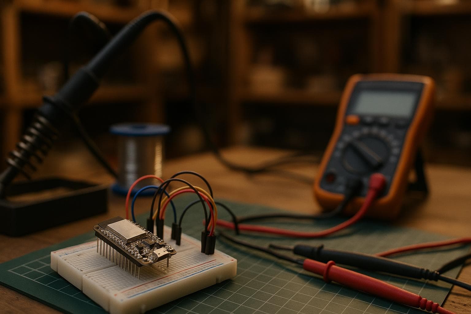
The board boots on the bench, then resets when WiFi transmits, refuses a firmware upload, or reports less memory than the listing promised. The honest answer is that a cheap ESP32 board is often usable, but its substituted support parts set the limits; identify those parts before changing your design.
Start with the symptom you can reproduce
Do not begin by replacing the board. First make the failure repeatable with a short test sketch, a known-good data cable, and a measured supply. Record the ESP32 variant printed by the chip or reported by the tool, the exact reset message, and whether the fault occurs during flashing, startup, or radio activity.
A useful first pass is:
- Disconnect sensors, displays, relays, and long wires.
- Power the board from the same source used in the final build, then repeat from a known USB port.
- Capture serial output at the failure, including brownout messages and watchdog resets.
- Run a WiFi transmit test separately from a flash-write test.
- Read the chip identification and memory map before trusting the product listing.
The cheapest and most common fault is usually the USB path, followed by the regulator and power wiring. Memory claims are quick to verify. Antenna performance takes more equipment, so check it after the digital board passes its basic tests.
Upload failures: identify the USB-serial chip first
Many clone dev boards substitute a CH340, CH341, CP2102, or CH9102 for the USB-serial interface found on another board. Those parts can work perfectly, but the driver, cable, voltage level, and boot-mode circuit all matter. Some ESP32 variants, including boards based on chips with native USB support, may use the ESP32's own USB interface instead of a separate bridge, so do not assume every USB connector has the same path.
Confirm the actual bridge in the operating system's USB device information, not from the listing. On Linux, lsusb gives the vendor and product identifiers; on Windows, the device properties show the hardware identifiers. Compare those identifiers with the bridge manufacturer's documentation. Then check the board's schematic or trace the bridge's TX, RX, DTR, and RTS connections if the schematic is unavailable.
A loopback test can confirm the USB bridge and cable: disconnect the ESP32 side if practical, connect the bridge's TX to RX at the logic voltage it is designed for, and verify that typed characters return. Do not short pins on an unknown board without checking the connector and voltage first. If loopback works but flashing fails, hold the ESP32 in download mode manually while starting the upload. A missing or weak auto-reset circuit is then more likely than a bad USB chip.
For a board used only to flash firmware and print logs, a CH340 is good enough. Buying a board with a different bridge does not fix a boot-mode wiring fault, and replacing a working driver-supported bridge is money spent on a problem you do not have.
Resets during WiFi: test the regulator before blaming the ESP32
The on-board regulator is often the real limit during WiFi transmit bursts, not the microcontroller. The ESP32 can be functioning correctly while a small regulator, thin USB trace, polyfuse, cable, or connector lets the supply rail dip below what the board needs.
First measure the rail feeding the ESP32, not just the 5 V input. Use an oscilloscope with a short ground spring if available. A multimeter may show a normal average voltage while missing a short transmit-burst dip. Run a repeatable WiFi operation such as association followed by sustained traffic, and compare the rail at idle and during transmission. A brownout reset in the serial log supports a supply problem, but its absence does not clear the regulator.
Check the regulator's marking and read its datasheet for maximum output current, dropout voltage, thermal limits, and required capacitors. The board's input current is not the same as the ESP32's radio current: LEDs, sensors, USB circuitry, and any attached load consume part of the regulator's capacity. A regulator can also pass a short test when cool and fail after its temperature rises.
This table is useful for separating the common substituted parts by the failure they create:
| Substituted part or condition | Electrical symptom | Confirmation test | Design consequence |
|---|---|---|---|
| USB-serial bridge or driver | Upload errors, missing serial port, unreliable auto-reset | Identify USB hardware, run bridge loopback, enter download mode manually | Keep the bridge if it is supported; fix driver or boot wiring first |
| Linear regulator with limited current or thermal margin | Brownout or reset during WiFi transmit | Scope the ESP32 rail during radio traffic; check regulator datasheet and temperature | Use a supply path with measured burst and thermal margin |
| Smaller or different flash device | Firmware will not fit, wrong partition map, failed OTA or filesystem setup | Read JEDEC ID and detected capacity with the flashing tool | Select partitions from detected capacity, not the listing |
| Missing or smaller PSRAM | Allocation failure, camera or frame-buffer crash, application instability | Query chip features and test a PSRAM allocation | Make PSRAM optional in software or choose a verified variant |
| Antenna network or layout mismatch | Weak range, low throughput, inconsistent RSSI by enclosure | Compare board revision, inspect RF parts, measure with a VNA or controlled link test | Preserve the RF keepout and match the tested enclosure |
Do not cure a regulator fault by adding a larger capacitor at random. Extra capacitance can help with local transient impedance, but it cannot repair a regulator that is thermally undersized, has excessive dropout, or is fed through a poor USB path. Measure the rail at the ESP32 and work backward toward the connector.
Read flash and PSRAM from the chip
Flash size and PSRAM presence can be read back from the chip, which beats trusting a product listing. The exact command depends on the ESP32 family and software tool, but esptool can identify the chip and read the flash JEDEC ID and detected capacity. In ESP-IDF, esp_chip_info() reports chip features, while PSRAM support is exposed through the relevant heap and SPIRAM APIs. Arduino-based firmware can report chip information through the ESP32 core, although the available calls vary by core version.
Use the result to choose the partition table and memory strategy. A listing that says “4 MB” may describe the flash on one revision while another revision carries a different device. A board may also have the same ESP32 family name but a different package, radio feature set, or PSRAM arrangement. The flash ID tells you what is physically responding; it does not make an incompatible partition table safe.
For PSRAM, check both the reported feature and an allocation test. A reported presence does not guarantee that every library is configured to use it. Allocate a known buffer through the framework's PSRAM-aware path, verify its address and available heap, then run the actual camera, display, or networking workload. If the application works without PSRAM, do not pay for an upgrade that fixes no present constraint. Designing for optional PSRAM usually makes a prototype easier to move between board revisions.
Weak WiFi: verify the antenna match, not just RSSI
A clone can copy the ESP32 and still alter the RF section. The antenna shape, impedance-matching network, ground clearance, connector transition, and nearby copper all affect the result. A missing component, wrong capacitor value, or changed PCB revision can reduce range without causing a software error.
Start with visual inspection under magnification. Compare the antenna end of the board with the maker's reference layout if one exists. Look for unpopulated matching components, solder bridges, copper under the antenna, a damaged meander, or an enclosure wall too close to the radiator. Confirm whether the board uses a PCB antenna or an external connector, and check that any antenna-selection resistor is populated in the intended position.
RSSI alone is not an antenna test. It varies with access point position, channel, polarization, transmit power, and reflections. For a useful bench comparison, keep the access point, channel, orientation, distance, and firmware fixed, then compare packet loss and throughput against a known board. A vector network analyzer with the proper fixture can measure return loss, but a bare-board measurement is not the same as the installed antenna inside its final enclosure. If RF performance matters, test the assembled product, not just the loose PCB.
The antenna match is the one check not worth buying a dedicated instrument for if WiFi is already reliable at the required distance. Use a controlled link test first. Buy or borrow RF test equipment only when the measured symptom justifies it.
Design around evidence, not the listing
Once each fault has a confirming test, write the board's limits into the design notes: detected flash capacity, PSRAM status, regulator rail under transmission, USB bridge type, and antenna arrangement. Keep a known-good firmware image that reports those values at boot. That turns a future replacement board into a comparison exercise rather than a guessing exercise.
Our preference is to buy the least expensive board that passes those tests, then leave margin in the power path and software. A clone dev board with a supported CH340, confirmed flash, no PSRAM requirement, and stable WiFi can be the right choice. The board becomes a bad bargain only when its undocumented substitutions force you to debug around them.
Frequently asked questions
How can I tell whether an ESP32 board has PSRAM?
Read the chip features with the ESP-IDF APIs or the board's ESP32 framework, then confirm with a PSRAM-aware allocation test. Do not infer PSRAM from the board name, silkscreen, or product listing.
Why does my ESP32 reset only when WiFi starts?
Measure the regulator output at the ESP32 during transmission with an oscilloscope. A supply dip, regulator dropout, USB cable loss, or thermal limit is more likely than a defective microcontroller, especially if the board is stable with the radio idle.
Is a CH340 USB interface a reason to reject a clone dev board?
No. If the operating system has the correct driver, loopback passes, logic levels are correct, and automatic or manual boot mode works, the CH340 is adequate for flashing and serial logs.
The Boss Factory builds made-to-order custom electronics and smart systems, 3D printing and prototyping, and design and product development through /quote.
Related services
All services →
Have a project in mind?
Tell us what you want built — we reply within 24–48 hours.