
RP2040 vs ESP32: PIO, Radio, and Real Build Trade-offs
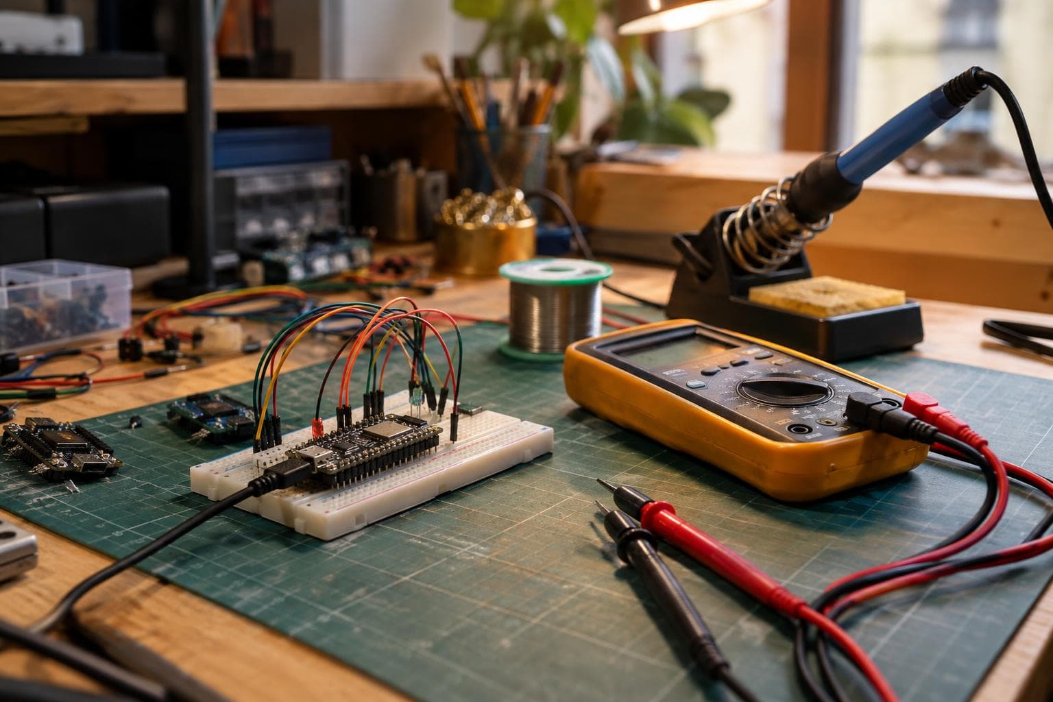
A small networked LED status panel looks easy until the requirements collide: exact LED timing, wireless control, a clean enclosure, and a build that does not consume the whole weekend. For most connected panels, we would pick an ESP32; for wired panels with demanding signal timing, the RP2040 earns its place through PIO, not through a radio it does not have.
Start with the actual panel requirement
Use a concrete target: a 100 mm square panel with an 8×8 addressable LED matrix, one push button, USB power, and a small enclosure. It might show machine state, a room status, or a changing counter. The controller needs to generate the LED data stream, read the button, and perhaps receive commands from a phone or local network.
That last requirement separates the parts immediately. The RP2040 has no radio on the die. A standard Raspberry Pi Pico based on RP2040 has no Wi-Fi or Bluetooth unless a separate radio board is added. Raspberry Pi Pico W adds wireless through a separate CYW43 module; the radio is not part of the RP2040 silicon.
Many ESP32 variants include wireless, but the exact radio depends on the variant. An original ESP32 module commonly provides Wi-Fi and Bluetooth Low Energy, while other family members differ in Bluetooth support, peripherals, memory, and power behaviour. Check the module and chip datasheet rather than treating “ESP32” as one fixed specification.
For a panel that needs a web page, MQTT, Bluetooth control, or an over-the-air update path, the ESP32 removes a board, a communication interface, and a large amount of firmware integration. That is a real reduction in build time, even if the RP2040 board itself costs less.
Where RP2040 PIO changes the decision
The RP2040 has two PIO blocks, each with four state machines for timing-exact IO. That gives eight PIO state machines in total. Each state machine runs a small dedicated program and can shift, wait, sample, and drive pins with timing that is much less exposed to ordinary application-code jitter.
That matters for signals such as WS2812-style one-wire LED data, parallel LED matrix interfaces, unusual serial formats, pulse measurement, and bitstreams that do not fit a standard UART, SPI, or PWM peripheral. A PIO program can keep producing the waveform while the two Cortex-M0+ cores handle animation, input, or protocol work.
PIO is not a magic cure for every timing problem. The output still depends on the RP2040 clock configuration, the PIO program, pin routing, signal integrity, and the receiving device's tolerance. Start from the receiving part's datasheet, then verify the waveform with a logic analyser or oscilloscope. A waveform that looks correct at the controller pin can still fail after a long cable, a poor ground connection, or an overloaded supply.
For this panel, RP2040 is the better technical choice if all of the following are true:
- The panel is controlled over USB, UART, RS-485, or another wired link.
- The LED protocol or matrix scan benefits from a dedicated timing engine.
- You want the firmware to keep running predictably while the display updates.
- A separate wireless board would add no useful function.
If wireless is required, adding a CYW43-equipped Pico W is a valid RP2040 design, but it changes the cost, software, antenna, enclosure, and power decisions. At that point, compare the complete boards rather than the bare microcontroller names.
ESP32 wins the connected version
For the same 100 mm panel with wireless control, we would use an ESP32 module or development board first. The radio is already part of the module or board design, and the software stack supports the common network tasks the panel needs. That leaves the firmware to deal with the display, input, provisioning, and failure handling rather than a second processor or external radio link.
The trade-off is timing architecture. ESP32 firmware has interrupts, radio activity, background stacks, and variant-specific peripherals to account for. That does not make it unsuitable for addressable LEDs. It means the display driver should use an appropriate hardware peripheral or a library designed for the exact ESP32 variant, rather than relying on a hand-timed loop that happens to work on the bench.
Radio also adds failure modes that a wired RP2040 panel does not have:
- The access point may be unavailable during startup.
- Credentials may need provisioning and storage.
- The antenna area must not be blocked by a metal object or badly arranged enclosure hardware.
- Network reconnect logic can interfere with a display task if the firmware has no clear scheduling boundary.
- Radio transmit bursts can expose weak 3.3 V regulation or poor decoupling.
An ESP32 does not automatically make a better product. It makes the connected requirement cheaper in parts and labour. If the panel has no network function, the radio is unused hardware and a source of software and power complexity.
Match the enclosure method to the panel
The electronics choice and the enclosure choice should be made together. A laser-cut acrylic box is quick to revise, gives a clean face, and makes the LED grid easy to inspect. Its weak points are exposed edges, visible fasteners, and stress around small slots. Acrylic can crack if holes are too close to an edge or if screws are tightened against it without clearance.
A 3D-printed enclosure handles curved backs, cable strain reliefs, snap fits, and captive nuts more easily. Its finish depends on layer height, wall orientation, first-layer control, and post-processing. A front bezel printed with the LED openings in the build plane can look clean, while a large flat face printed across unsupported spans can show warping or uneven texture.
For one panel, we normally choose the enclosure method by the feature that is hardest to make:
- Choose laser-cut acrylic for a flat, transparent or translucent face with simple rectangular geometry.
- Choose 3D printing for integrated bosses, clips, angled faces, cable channels, or a shape that needs several revisions.
- Use a separate diffuser when LED hotspots matter; changing the diffuser is cheaper than redesigning the controller.
- Leave service access for the USB connector, reset button, and any removable wiring.
- Keep the radio antenna area clear on an ESP32 or Pico W design, especially if the enclosure includes conductive hardware.
The finish is not only cosmetic. A bright LED behind a rough or poorly spaced diffuser creates hot spots that make the panel look uneven. A glossy face shows fingerprints and scratches more readily than a satin surface. A printed enclosure can hide fasteners and wiring, while a laser-cut enclosure can make alignment and internal clutter visible. Pick the construction method after deciding what the viewer will see.
Test the controller, LED load, power supply, button wiring, and communication behaviour on an open fixture before finishing the case. Measure voltage at the first and last LED under the brightest intended pattern. Confirm that the regulator remains within its rated temperature and that the USB cable and connectors do not become the limiting conductors.
Then test the exact controller board inside the planned enclosure. For ESP32 or Pico W, check connection and recovery with the lid installed. For RP2040, check the LED waveform with the final cable length and connector. Run the display while switching patterns, pressing the button, unplugging the network, and restarting power. These tests expose design faults while changing a wire is still easier than changing a finished face panel.
RP2040 vs ESP32 for this exact build
| Technical axis | RP2040 route | ESP32 route |
|---|---|---|
| Wireless | None on the RP2040 die; add a separate radio board such as Pico W's CYW43 module | Wireless is integrated on many ESP32 modules, but Wi-Fi and Bluetooth features vary by chip variant |
| LED timing | Two PIO blocks, four state machines per block, useful for dedicated waveform generation | Use a suitable hardware peripheral or variant-specific driver; avoid assuming every ESP32 has the same peripheral set |
| Firmware timing | Display generation can be isolated in PIO while the cores handle other work | Radio stacks and interrupts require clearer task boundaries and testing under network activity |
| Current budget | The LED matrix usually dominates current; board and radio choice still affect idle and peak draw | Radio transmission adds peaks, so regulator capacity, decoupling, and supply wiring need more margin |
| Enclosure tolerance | Wired-only designs allow fewer antenna-clearance constraints | Antenna placement and enclosure material can affect range and connection stability |
| Build time | Fast for a wired panel; longer if a separate radio or protocol bridge is added | Fastest for a connected panel because the radio and network support are already part of the design |
| Cost per part | Often attractive when the design needs no wireless and uses PIO directly | Often attractive for networked units because a second communication board is avoided |
| Main failure mode | Choosing it for wireless, then discovering the radio and software integration dominate the project | Choosing it for a simple wired display, then carrying unused radio and network complexity |
For the stated panel, our pick is the ESP32 if it must be controlled over Wi-Fi or Bluetooth. Our pick is the RP2040 if it is a wired display, especially if the LED protocol, matrix scan, or pulse output benefits from PIO. That is the useful answer in the RP2040 vs ESP32 decision: radio requirement first, timing architecture second, board price third.
Quantity does not create a reliable flip by itself. From one prototype through a small run, the same rule holds because the engineering and firmware choice dominate. At larger quantities, calculate the complete assembled bill of materials, programming time, test fixture, connector count, enclosure labour, and failure-test time. The answer flips to RP2040 only when wireless is removed and its lower-complexity wired design produces a measurable per-unit saving. It flips to ESP32 when adding a separate radio, bridge board, or extra assembly step costs more than the ESP32 premium.
Do not buy an external logic analyser because the board name sounds difficult, but do use one before blaming the chip. Do not add Pico W wireless to a panel that already has a wired control path. That upgrade fixes a problem you do not have. Conversely, do not choose a bare RP2040 for a panel whose first requirement is phone control and expect PIO to compensate for missing radio hardware.
Frequently asked questions
Does the RP2040 have Wi-Fi or Bluetooth built in?
No. The RP2040 has no radio on the die. A Raspberry Pi Pico W adds wireless with a separate CYW43 module, so Pico W is a different board-level solution from a bare RP2040 board.
Is RP2040 PIO better than ESP32 for WS2812 LEDs?
PIO is a strong fit when you need predictable waveform generation and want display timing separated from application code. ESP32 can also drive WS2812 LEDs, but the correct method depends on the exact ESP32 variant and its available hardware peripherals. Test the chosen driver under radio activity rather than judging from a static bench pattern.
Which board should I use for a wireless LED panel?
Use an ESP32 for the shortest path when its supported radio features match the requirement. Use Pico W when RP2040 PIO is central to the design and the CYW43 wireless hardware and software support fit the project. Use a standard RP2040 board only when the panel is wired or a separate radio is deliberately part of the architecture.
The Boss Factory builds made-to-order networked controllers and enclosures through Custom Electronics & Smart Systems, 3D Printing & Prototyping, and Design & Product Development at /quote.
Have a project in mind?
Tell us what you want built — we reply within 24–48 hours.