
- pwm
- esp32
- ledc
- motor control
- servo control
PWM Frequency and Resolution: The Timer Trade-Off
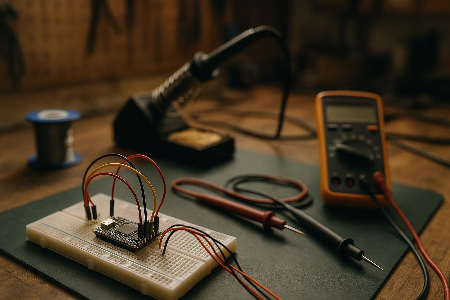
A PWM output cannot have unlimited frequency and unlimited duty-cycle resolution from the same timer. The timer has to count between one rising edge and the next, so increasing the frequency shortens the counting window and removes available steps. The honest answer is to choose the frequency from the load first, then use every resolution bit that still fits.
How a PWM timer creates resolution
A PWM timer runs from a clock, counts upward, and changes the output at programmed compare points. The period ends when the counter reaches its top value, then the sequence starts again. Duty cycle is the fraction of that period for which the output is high.
If a timer has a usable count range of 0 through 255, it can represent 256 duty settings, often described as 8-bit PWM. A 12-bit range provides 4096 settings. The useful relationship is:
period counts = timer clock frequency / PWM frequency resolution bits = floor(log2(period counts))
That relationship is an ideal limit. Prescaler choices, a fixed counter top, center-aligned counting, dead time, and the peripheral's register format can reduce the result. The physical rule does not change: available PWM resolution is set by how many timer counts fit into one period, so a higher frequency leaves fewer usable bits.
At 1 kHz, a timer clocked at 1 MHz has about 1000 counts per period, which is just under 10 bits. At 20 kHz, the same timer has about 50 counts, which gives only 5 bits if the timer must use a power-of-two count range. A faster timer clock can recover some of that resolution, but the clock and divider limits belong to the particular microcontroller.
The smallest duty-cycle step is roughly one period count. With 1000 counts, a one-count change is about 0.1 percent duty. With 50 counts, it is about 2 percent. That step size is what the load sees, even if the software variable is stored as a 16-bit number. A 16-bit value mapped onto a 50-count timer is still only about 50 real output positions.
What this means on an ESP32
On the ESP32, hardware PWM is generated by the LED Control peripheral, usually called LEDC. It is not produced by the analogWrite mechanism found on classic 8-bit boards. The Arduino-ESP32 core may expose convenience functions whose names vary by core version, but the underlying PWM resource is LEDC, with hardware timers, channels, frequency, and duty resolution.
That distinction matters because LEDC ties frequency and resolution to a selected timer configuration. Channels assigned to the same LEDC timer share its frequency and duty-resolution settings. A change intended for one output can therefore affect another output if both channels use that timer. Check the core version's LEDC API and the ESP32 variant's peripheral documentation rather than copying an example written for an older Arduino core.
A useful setup sequence is:
- List the required PWM frequencies before assigning pins.
- Group outputs that can share a timer, such as several LEDs using the same carrier frequency.
- Calculate the count requirement from the timer clock and target frequency.
- Select the highest resolution that the peripheral can actually sustain at that frequency.
- Confirm the duty-register width and maximum duty value in the documentation for the ESP32 variant and framework version.
- Scope the pin and measure the real period and duty cycle after configuration.
High-speed and low-speed timer behavior, clock-source selection, and available resolution vary by ESP32 family member. An ESP32, ESP32-S2, ESP32-S3, and ESP32-C3 should not be treated as interchangeable for peripheral details.
Choosing PWM for LED dimming
LED dimming usually needs a frequency high enough that the eye does not see individual pulses and that the camera does not produce objectionable banding. A starting range around several hundred hertz to a few kilohertz works for many visible indicators and architectural LED loads, but the correct value depends on the LED driver, switching device, wiring, and camera exposure.
The load may contain its own regulator or constant-current circuit. Some drivers expect a specified PWM input frequency and duty range. Others filter the signal or interpret a low-frequency enable input differently from a fast dimming input. The driver datasheet takes priority over a generic microcontroller example.
For ordinary indicator lighting, the cheap way is usually good enough: a suitable few-kilohertz carrier with 8 to 12 effective bits is often more useful than a high-frequency, high-resolution controller that the driver cannot reproduce. A camera installation or a sensitive optical measurement system can justify a higher carrier, but measure the camera result before selecting it.
Choosing PWM for motor drive
Motor PWM is a power-switching decision, not just a brightness-control decision. The frequency affects current ripple, switching loss, acoustic noise, diode recovery, electromagnetic interference, and the control loop's available update time.
A brushed DC motor may run acceptably from a few kilohertz upward. Many designs choose a frequency above the most objectionable audible range, often in the roughly 16 to 25 kHz region, but that is a starting band rather than a universal prescription. The motor inductance, supply voltage, MOSFET, gate driver, load inertia, and thermal path decide whether that choice is sensible.
A three-phase inverter has additional constraints. Dead time must prevent high- and low-side switches in one leg from conducting together. Center-aligned PWM can reduce some waveform asymmetry and is common in motor-control peripherals, but it changes the relationship between timer counts and the stated carrier frequency. Some control schemes also need synchronized ADC sampling at a known point in the PWM cycle.
| Application | Practical starting frequency | Resolution concern | Main failure mode to test |
|---|---|---|---|
| Visible LED dimming | Hundreds of hertz to a few kilohertz | Enough steps for the driver and the desired low-light range | Flicker, camera banding, or unstable low duty |
| Brushed DC motor | A few kilohertz to roughly 25 kHz | Current-control steps must be smaller than the loop can resolve | Excess heat, audible whine, current ripple, or EMI |
| RC servo command | Usually 50 Hz for legacy analog-style inputs | Pulse-width tick size matters more than total duty bits | Wrong pulse limits, jitter, or a servo that rejects the frame rate |
If the motor controller closes a current or speed loop, calculate how much duty change corresponds to a meaningful current change. Five effective bits may be inadequate for fine current control even if the motor spins. Conversely, adding bits at a frequency that makes the MOSFET waste excessive switching power is a poor trade. Measure switch temperature, motor current ripple, and the actual pin waveform under load.
Choosing PWM for servo control
A conventional hobby servo does not use PWM in the same sense as a motor speed controller. It usually measures the width of a command pulse repeated at a frame rate, with 50 Hz being common for legacy analog-style servos. The pulse width, not the average duty ratio, represents the requested position.
At 50 Hz, the frame is 20 ms long. A timer with 1 microsecond ticks can represent pulse changes in 1 microsecond increments, which is generally a more useful specification than saying the signal has a certain number of duty bits. The servo's internal electronics, gear backlash, deadband, supply voltage, and mechanical load can be much coarser than the timer.
Some digital servos accept higher frame rates, but the allowable range is a servo-specific datasheet property. Do not raise the rate because a timer can generate it. A servo may ignore the command, behave unpredictably, or draw current differently if its expected frame timing is exceeded.
Set the pulse range conservatively, verify the servo's stated limits, and test travel without forcing the linkage against a stop. For a servo output, stable timing and correct pulse width matter more than maximizing nominal PWM resolution. On an ESP32, reserve a timer configuration that gives a convenient pulse-width tick and keep unrelated high-frequency outputs from sharing that timer.
A bench method for selecting the setting
Start with the load's requirement, not the largest number in the API. Write down the minimum acceptable frequency, the maximum frequency the driver or actuator permits, and the smallest useful duty or pulse-width change. Then calculate the count budget.
For a peripheral with timer clock F and target frequency f, estimate F / f. If the result is 2048 counts, 11 bits is the practical power-of-two resolution. If it is 300 counts, a peripheral that supports an arbitrary top value may offer more usable steps than a fixed 8-bit or 9-bit mode, but confirm the register behavior.
Measure three things on the assembled circuit:
- Frequency and duty at the pin with an oscilloscope or logic analyzer.
- Voltage and current at the load during low, middle, and high duty.
- Temperature and audible or visible artifacts after the load has reached its normal operating condition.
Change one variable at a time. If raising frequency reduces motor ripple but increases switch temperature, the timer trade-off is behaving exactly as expected. If changing duty produces no measurable load change, extra software resolution is not buying control.
Frequently asked questions
Does higher PWM frequency always reduce resolution?
It reduces the available count budget when the timer clock stays the same. A different clock source, divider, or timer mode can change the exact result, but the period still has to contain the timer counts that represent duty. Higher frequency cannot provide more counts from an unchanged clock and unchanged hardware limits.
Is 16-bit PWM really 16-bit on an ESP32?
Only if the selected LEDC timer configuration can fit 65,536 usable counts in the requested period and the ESP32 variant supports that combination. A 16-bit software duty value may be scaled to a smaller hardware range. Check the configured frequency, resolution, clock source, and variant-specific LEDC limits, then measure the output.
What PWM frequency should a servo use?
Use the servo manufacturer's specified frame-rate range. Around 50 Hz is common for conventional RC servo command signals, but digital servos can accept other rates and some do not. Pulse-width limits and timing stability matter more than selecting the highest possible bit count.
The Boss Factory builds made-to-order custom electronics, LED systems, and software work; request that work at /quote.
Related services
All services →
Have a project in mind?
Tell us what you want built — we reply within 24–48 hours.