
- current sensing
- shunt monitor
- hall effect
- current transformer
- ina226
- acs712
Current Sensing: Shunt, Hall, or Clamp Transformer?
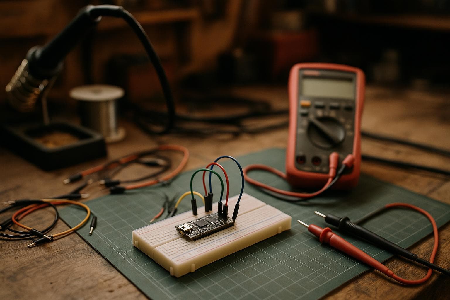
The right current sensor is decided less by its headline accuracy than by whether the circuit carries DC, whether you can interrupt it, and how small the current is. For low-current DC on a board, we would pick a shunt with a dedicated monitor; for isolated measurements without opening the circuit, Hall wins. A clamp-on transformer is the fastest choice for AC-only work, but it cannot measure steady DC at all.
Shunt current sensing gives the best low-current resolution
A shunt-based monitor measures the voltage across a small known resistance. Ohm's law does the conversion: current equals measured voltage divided by shunt resistance. A dedicated monitor chip measures that small differential voltage and usually handles gain, common-mode range, conversion, and bus communication better than a general-purpose ADC wired across a resistor.
This method gives the best resolution at low currents because the sensing range can be chosen around the current you actually need to resolve. A 10 mA change through a suitably sized shunt produces a measurable voltage change even when a Hall module's offset is larger than the signal. The trade-off is burden voltage and heat. Increasing shunt resistance improves voltage resolution but wastes more power and reduces the voltage available to the load.
A high-side monitor such as the INA226 is a particular example, not a universal description of every shunt monitor. Check the exact chip's common-mode voltage range, conversion settings, shunt-voltage range, bus interface, and allowed shunt power before copying a reference design. The INA226 also reports bus voltage and calculated power, but those features do not remove the need to size the resistor and layout for the expected current.
The circuit must be opened during installation because the shunt goes in series with the load. It is not galvanically isolated. The monitor's input pins remain tied electrically to the measured circuit, so isolation may require an isolated power supply, an isolated data link, or a different sensing method.
For a finished board, the shunt is usually the neatest option. A low-value resistor and a small monitor IC can sit close to the load path, with no protruding magnetic core or separate sensor board. Keep the high-current copper short, use Kelvin connections to the shunt where the resistor supports them, and keep load current out of the voltage-sense traces. A poor layout can erase the advantage of the monitor's nominal resolution.
Hall-effect modules trade low-current accuracy for isolation
A Hall-effect sensor measures the magnetic field produced by current. The conductor and signal electronics can remain galvanically isolated, which is the main reason to choose it. The measured wire does not need to be cut, and a module can often be added around an existing conductor with less rework than a series shunt.
The price of that convenience is offset and drift. Hall offset and temperature drift can swamp small currents, especially with an inexpensive module intended for a larger nominal current. A module rated for tens of amperes may be a poor instrument for tens of milliamperes even if its output appears stable on a multimeter. Zero the sensor under the actual temperature and mechanical arrangement if the application permits it, then verify the result over the temperature range that matters.
The common search comparison, “acs712 vs ina226,” is not a direct accuracy contest. The ACS712 is a Hall-effect current sensor family with galvanic isolation; its sensitivity, bandwidth, noise, and error figures depend on the exact variant and supply conditions. The INA226 is a shunt monitor and therefore requires a series shunt and an electrically connected measurement path. An ACS712 can measure both current polarities around its zero point, while an INA226 setup is governed by the shunt, monitor range, and circuit polarity. Pick by isolation and installation constraints before comparing ADC resolution.
Choose Hall sensing when one of these conditions is real:
- The measured circuit cannot be interrupted during normal installation.
- The sensing electronics must be isolated from a hazardous or floating voltage.
- The current is large enough that a practical shunt would dissipate too much power.
- Bidirectional DC measurement is needed and the sensor's offset can be calibrated.
- A removable conductor or service loop makes mechanical installation easier than PCB rework.
Do not buy an isolated Hall module to solve a small-current problem that a shunt already solves. That upgrade can add offset, drift, noise, and cost while fixing no constraint you actually have.
Clamp-on transformers are for changing AC current
A clamp-on current transformer is a magnetic transformer with a split core that closes around a conductor. The conductor acts as the primary, so the circuit does not need to be broken. The secondary produces a current or voltage proportional to the changing primary current, depending on the burden resistor and readout circuit.
This method is isolated and convenient, but it measures AC rather than steady DC. A sine wave, switched waveform, or pulsed load can be measured only within the transformer's frequency range and crest-factor limits. A constant DC load produces no sustained transformer output. A changing transient can produce a response, but that is not the same as measuring its DC level.
The clamp's low-current performance depends on core material, turns ratio, burden, noise, and the frequency of the waveform. At low frequency, the core has less changing flux per cycle and the response can fall away. At high current or excessive burden, the core can approach saturation and distort the waveform. Read the frequency-response and maximum-primary-current information for the exact part rather than treating all clamp transformers as interchangeable.
For a temporary measurement, this is often the fastest method: close the clamp, connect the burden and safe input circuit, and observe the waveform. The finish is less attractive in a compact product because the hinge, cable, and clearance around the conductor need room. Mechanical strength also matters. A clamp that does not fully close changes the magnetic path and can make readings inconsistent.
A clamp transformer is the wrong choice for battery draw, USB standby current, a DC motor's steady state, or any control loop that needs a DC reading. A Hall sensor can cover DC with isolation; a shunt can resolve smaller DC values. The transformer earns its place when the signal is AC and avoiding a circuit break matters more than measuring down to zero.
Compare the methods before drawing the enclosure
The following comparison is about the measurement path, not a particular product board. “Low-current result” still depends on the exact sensor, shunt value, amplifier or ADC, wiring, temperature, and calibration.
| Method | Current type | Isolation | Low-current result | Circuit break | Integration cost and finish | Main failure mode |
|---|---|---|---|---|---|---|
| Shunt plus monitor chip | DC and AC within the monitor's bandwidth | None unless added elsewhere | Best resolution when the shunt and gain are sized for the small current | Yes, series installation | Lowest part cost and cleanest PCB result; layout takes care | Burden voltage, heating, common-mode error, or noisy Kelvin routing |
| Hall-effect module | DC and AC within the exact sensor's bandwidth | Galvanic isolation | Offset and drift can swamp small currents | No | Fast to add; module height and connectors affect enclosure finish | Zero error, temperature drift, magnetic interference, or conductor overrange |
| Clamp-on transformer | Changing AC only | Galvanic isolation | Often weak at low frequency or low current; no steady-DC reading | No | Fastest for temporary AC tests; clamp size affects fit and appearance | Core saturation, incomplete closure, wrong burden, or out-of-band waveform |
Time and quantity change the decision. For one bench measurement, use the method already matched to the signal. A ready Hall module or clamp transformer can save design time even if its component cost is higher. For repeated low-current DC assemblies, a shunt footprint and monitor chip usually repay their layout work through smaller packaging, repeatable calibration, and better resolution.
There is no honest universal quantity at which the answer flips. The crossover depends on whether a PCB already exists, how much enclosure work the sensor needs, whether isolation testing is required, and whether each unit must be calibrated. In practice, the more often the same low-current DC measurement is built, the stronger the case for a designed-in shunt. For occasional isolated AC checks, a clamp remains cheaper in engineering time even when a custom board would look cleaner.
Use this selection order:
- Identify DC, AC, or a waveform with both components. Eliminate the transformer for a measurement that must include steady DC.
- Set the maximum current, minimum meaningful change, allowable burden voltage, and expected temperature range.
- Decide whether galvanic isolation is a requirement or only a convenience.
- Check whether the conductor can be interrupted and whether the enclosure has room for a clamp or module.
- Calibrate against a trusted meter or load at the temperatures and current levels that matter.
Our pick for the three common cases
For a low-current DC rail on a controlled PCB, we would use a shunt and a dedicated monitor chip. It gives the best resolution at low currents, keeps the assembly compact, and makes the error sources visible in the schematic and layout. The circuit break is a design-stage decision rather than a field-installation problem.
For a high-current or floating circuit where isolation is mandatory, we would use a Hall sensor after checking its offset against the smallest current of interest. If that smallest current is close to the sensor's zero error, the method is wrong no matter how convenient the installation is.
For non-invasive AC waveform checks, we would use a clamp-on transformer and verify its frequency response and burden circuit. It is not a cheaper substitute for a DC sensor; it is a different instrument with a narrower job.
Frequently asked questions
Is a shunt resistor more accurate than a Hall-effect sensor?
For small, stable currents, usually yes, because the shunt signal can be selected and amplified around the operating range. Accuracy still depends on resistor tolerance, temperature coefficient, monitor error, layout, calibration, and burden voltage. A Hall sensor may be the better measurement when isolation or a no-break installation is mandatory.
Can a clamp-on transformer measure battery current?
Not the steady battery current. A current transformer responds to changing magnetic flux, so it can show ripple or transient components but not the DC level. Use a shunt or a Hall sensor for a battery measurement that must include the average current.
Does a Hall sensor need calibration at zero?
Usually, yes, if small currents matter. Offset varies by sensor variant, supply, temperature, mounting, and nearby magnetic fields. Record the zero under the actual installation conditions, then check a known current in both directions if the application is bidirectional.
We build made-to-order current-sensing work through Custom Electronics & Smart Systems.
Related services
All services →
Have a project in mind?
Tell us what you want built — we reply within 24–48 hours.