
- internal wiring
- serviceable design
- electronics
- maintenance
- cable management
Internal Wiring: Build a Box You Can Service
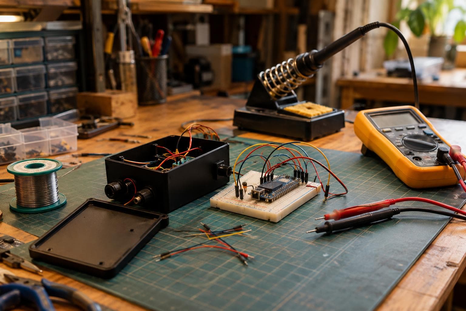
A box can work perfectly on the bench and still be badly wired. The real test is whether you can reach the board, trace a cable, and replace a failed part without dismantling half the enclosure. The honest answer is straightforward: leave a deliberate service path, control routing, label both ends, and choose connectors only where they save future work.
Design internal wiring around the next repair
Start with the board, power entry, heat sources, antennas, moving parts, and anything likely to be replaced. Route cables so the enclosure can open without pulling on a solder joint or trapping a wire under a lid.
A service loop is a deliberate length of spare cable near a board or connector. Size it so the board can be lifted out and worked on without unplugging or unsoldering anything. That is the useful definition. A loop that only lets you move a board 10 mm before the harness goes tight is decoration, not serviceability.
Leave enough slack for the board to clear mounting posts, headers, and enclosure walls. Keep the loop supported so it cannot sag into a fan, hinge, heatsink, sharp edge, or terminal. Do not coil high-current conductors into a tight bundle just to make them look tidy. A loose, supported bend is easier to inspect and usually sheds heat better.
Cable routing also affects electrical performance. Cables routed across an antenna keep-out area detune the antenna exactly as any conductor would. This applies to power, signal, shield drain, and unused wire. Follow the antenna and module manufacturer's keep-out geometry rather than assuming a low-voltage cable is harmless. If a cable must cross the area, change the mechanical layout first; ferrite beads and software settings are not substitutes for clearance.
Keep wiring away from heat-producing parts such as regulators, resistors carrying load, power transistors, motors, and LED drivers. Heat accelerates insulation ageing and can move a connector or adhesive-backed tie point out of position. Keep signal wiring away from high-current switching paths where practical, and cross noisy conductors at right angles rather than running parallel for a long distance.
Assembly checks that prevent hidden faults
Before closing the box, make the wiring legible without a schematic in hand. Label both ends of every cable that might be unplugged, replaced, or confused with another cable. The label should identify the destination and, where useful, the signal or voltage. A label on only the board end fails as soon as the harness is removed.
Use a label material and attachment method that survive the enclosure's heat, cleaning method, and flexing. A paper flag held by weak adhesive is not a permanent identifier. Heat-shrink labels are useful on loose wire, while flat printed labels suit larger harnesses. Do not hide the only label under a tie wrap or against the panel.
Our pre-close inspection is short and mechanical:
- Pull each cable gently at its termination to find unsupported joints.
- Check that no wire is pinched by a lid, standoff, fan guard, or cable gland.
- Confirm that every connector latch is engaged and every screw terminal has the specified strip length and tightening method.
- Verify polarity and continuity before applying power.
- Check that the service loop reaches its intended position without bending a board or loading a header.
- Photograph the finished routing before the cover goes on.
Maintenance routine by interval
At commissioning and after every wiring change
Inspect the full path with power removed. Confirm labels, strain relief, bend radius, clearance from heat, and antenna keep-out. Then test continuity and polarity before functional testing. These checks prevent reversed supply connections, intermittent open circuits, pinched insulation, and an antenna that works differently after the enclosure is assembled.
Move the board through its service position once. If the harness cannot support that movement without force, correct it immediately. This prevents the first repair from becoming a desoldering job.
Monthly or after heavy vibration, transport, or repeated access
Look for loosened screw terminals, backed-out connector latches, fretting marks, tie points cutting into insulation, and wires rubbing against metal or printed edges. Check that loops have not migrated into fans or hot zones. These inspections prevent intermittent faults that appear only when the enclosure moves or warms up.
Do not retighten every terminal by habit. Follow the terminal manufacturer's method and torque information where provided. Over-tightening can damage fine-stranded conductors or the terminal itself. If the connection shows heat discoloration, insulation damage, or repeated loosening, find the cause instead of tightening harder.
Every six to twelve months, or during planned service
Open the enclosure and compare the physical wiring with the current schematic or wiring record. Confirm that labels still match and that undocumented changes have not created duplicate ground paths, overloaded conductors, or blocked airflow. Check service loops after any board revision because a connector moved by one header can remove the spare length you thought you had.
Solder, connector, or terminal block
We choose a connector when the part is expected to be removed, the harness needs to be tested separately, or the box requires repeated service. We choose a soldered joint for a fixed, protected connection where adding a connector would create another failure point. A connector is not automatically better: it adds contacts, latch mechanics, clearance needs, and a possible unplugged state.
| Connection method | Temperature and current limits | Tolerance to movement | Main failure mode | Best service use |
|---|---|---|---|---|
| Soldered splice or wire-to-wire joint | Determined by wire, insulation, solder system, and joint design | Low unless strain-relieved | Fatigue at the joint or heat damage | Fixed harnesses that are rarely disturbed |
| Locking wire-to-board connector | Ratings are connector- and contact-specific; derate for heat and bundled current | Moderate with proper retention and support | Unseated latch, backed-out crimp, worn contact | Boards likely to be removed |
| Pluggable terminal block | Ratings are terminal-specific; verify conductor size, current, voltage, and temperature rise | Moderate; vibration needs retention and strain relief | Loose screw, poor strip length, damaged fine strands | Field-replaceable power and control wiring |
The decision is about the next repair, not appearance. If replacing a board requires a soldering iron, use a connector at the board boundary unless the connector creates a worse electrical or mechanical problem. If a connector would sit beside a heat source, vibrate continuously, or carry current beyond its verified rating, a properly supported soldered connection may be the safer choice.
Frequently asked questions
How much service loop should internal wiring have?
Enough to put the board or module in its intended service position without unplugging or unsoldering anything, while keeping the cable away from heat, fans, sharp edges, and antennas. The required length depends on the enclosure geometry and board mounting, so measure the removal path rather than adding a fixed percentage.
Can a cable cross an antenna keep-out area if it carries only power?
No assumption is safe. Cables routed across an antenna keep-out area detune the antenna exactly as any conductor would. Keep the route outside the specified area unless the antenna design documentation explicitly permits the crossing and the finished enclosure is tested in its final configuration.
Should every internal wire have a connector?
No. Use connectors where they shorten board replacement, harness testing, or recurring service. For a fixed, protected, low-vibration connection, a supported soldered joint can be cheaper and more reliable than adding contacts and a latch.
We build serviceable internal wiring for custom electronics and smart systems to order; request a quote.
Related services
All services →
Have a project in mind?
Tell us what you want built — we reply within 24–48 hours.