
- oscilloscope
- electronics
- logic analyser
- signal integrity
- hobbyist tools
Oscilloscope for Hobbyists: When to Buy a Scope
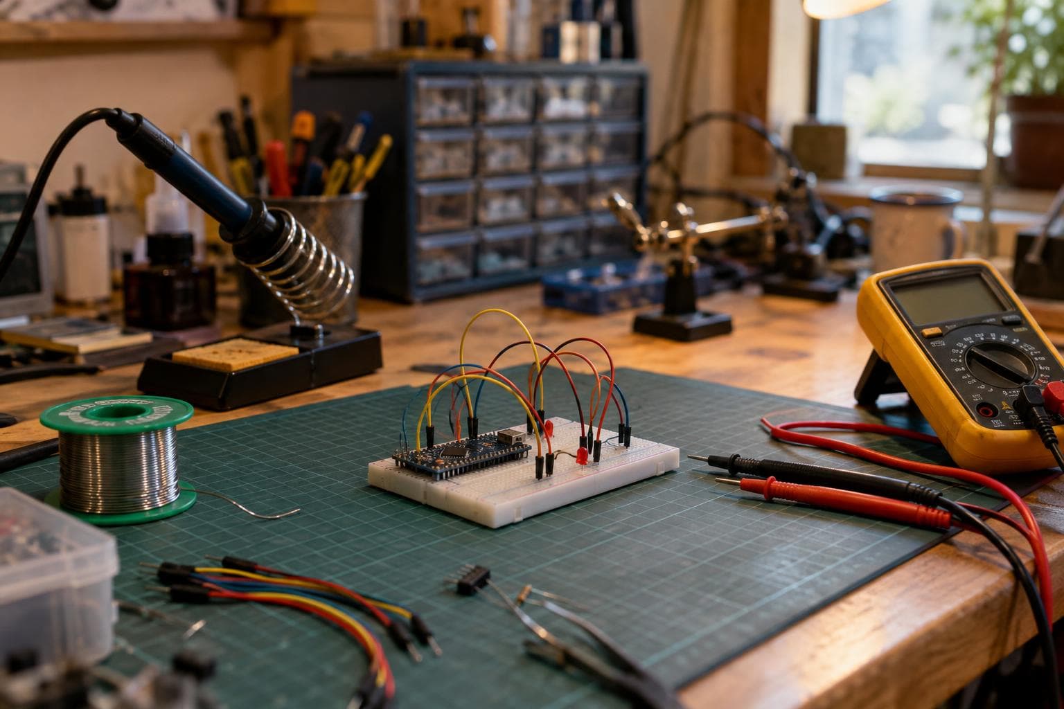
A meter can tell you that a supply reads 5 V, and a logic analyser can tell you that a digital message arrived. Neither tells you what happened between those observations. If a board resets, an ADC value wanders, or a data line works only sometimes, the honest answer is usually this: buy a scope only when the shape of the signal is part of the fault.
What each instrument can actually prove
A digital multimeter is the right first tool for static conditions. It checks continuity, resistance, DC voltage, diode drops, and current averaged over a relatively long interval. It can show that a rail is low, but a reading of 4.98 V does not prove that the rail stayed near 5 V during a radio transmission or motor start.
A logic analyser answers a different question. It samples a signal, compares it with a threshold, and reports digital states over time. That makes it useful for:
- Checking UART baud rate, framing, and parity.
- Seeing whether an I2C address is followed by an acknowledge bit.
- Measuring the interval between GPIO events.
- Finding firmware that sends the wrong byte or waits forever.
- Comparing a trigger signal with a protocol transaction.
A logic analyser normally cannot show whether a nominally high signal rose cleanly, crossed the threshold late, or dipped below it for a short period. Its display turns voltage into a one or zero. The threshold and sample rate also affect what it reports, especially on narrow glitches.
An oscilloscope shows signal shape over time, which is the only way to see ringing, overshoot, and ripple directly. It also shows rise and fall behaviour, slow edges, noise riding on a DC level, supply droop, and analog timing between two voltage events. That extra information is the reason to buy one, not the fact that it looks more advanced.
| Method | Time resolution | Signal information | Input loading | Best use | Failure it can miss | Relative purchase cost |
|---|---|---|---|---|---|---|
| Multimeter | Slow compared with switching edges | DC value, resistance, averaged current | Usually low for voltage measurement, but check the meter's current burden voltage | Power checks, continuity, static bias | Ripple, short drops, ringing, protocol timing | Lowest |
| Logic analyser | Sample-clock dependent digital timing | Threshold crossings and decoded states | Probe capacitance can affect fast lines | Digital protocols and firmware timing | Marginal voltage levels, overshoot, analog settling | Low to moderate |
| Oscilloscope | Continuous sampled waveform within its bandwidth | Voltage shape, timing, noise, ripple, edge quality | Probe capacitance and grounding matter | Analog behaviour and signal integrity | Events outside its bandwidth, poor triggering, current without a suitable sensor | Moderate to high |
Start with the failure, not the instrument
For a microcontroller board that resets when a load switches, begin with a meter. Confirm the supply polarity, idle voltage, regulator output, and ground continuity. If those pass, a logic analyser can confirm whether the reset is followed by a clean boot sequence and whether the firmware is producing the expected control signal.
The next question is not "does the rail read 5 V?" It is "what does the rail do at the instant of failure?" That requires a scope. Set the trigger near the suspected reset event, probe the supply at the board's decoupling capacitor, and compare the rail with the reset pin or load-control signal on another channel. A brief sag, a sharp positive spike, or a burst of ripple can be invisible to a meter and irrelevant to a logic analyser's digital trace.
This same split applies to sensors. A logic analyser can show that an ADC conversion starts on schedule, but it cannot prove that the analog input settled before the sample. A scope can show the sensor output, the switching waveform that disturbs it, and the conversion trigger together. That is analog timing: the relationship between a changing voltage and the instant another circuit acts on it.
A current problem needs care. A normal scope measures voltage, not current. A low-value shunt resistor plus a suitable differential measurement can estimate current, but the resistor changes the circuit and its power rating matters. A current probe avoids some of that disturbance but adds cost and bandwidth limits. Do not buy a scope expecting it to solve every current measurement without an appropriate method.
Bandwidth follows edge speed, not clock frequency
The fastest edge in the circuit matters more than the stated clock frequency. A 1 MHz square wave can have nanosecond edges, while a faster clock may have deliberately slowed transitions. The edge speed determines the high-frequency content that must pass through the probe and scope.
Usable bandwidth should be several times the fastest signal edge of interest. A common first estimate for the equivalent bandwidth of an edge is 0.35 divided by its 10-to-90 percent rise time. A 2 ns edge therefore has an equivalent bandwidth of about 175 MHz. If the shape of that edge matters, a scope and probe with several times that bandwidth are a more sensible target than a scope selected from the 1 MHz repetition rate.
That does not mean every hobby circuit needs a very fast instrument. If the question is whether a temperature sensor output takes 20 ms or 30 ms to settle, a modest bandwidth is enough. If the question is whether a 10 ns edge rings for several cycles, insufficient bandwidth can smooth away the evidence.
Probe choice is part of the bandwidth. A long ground lead adds inductance and can create ringing that is not present at the circuit node. Use the shortest practical ground connection, keep the probe tip at the point being measured, and check the probe's compensation on the scope's calibration output. The scope's headline bandwidth is not the bandwidth of a careless probing setup.
A practical decision at the bench
Use this sequence before spending money:
- Measure the static voltage and resistance with a meter.
- Decode the digital transaction with a logic analyser if the suspected fault is protocol or firmware timing.
- Identify the exact event that fails: reset, missed sample, false interrupt, noisy output, or unstable control loop.
- Ask whether voltage shape between two threshold crossings matters.
- If it does, use a scope and select bandwidth from the fastest edge, not the clock label.
- Repeat the test at the circuit pin, then at the power source, because cable and ground impedance can move the fault.
For many boards, the cheap way is good enough: a meter plus a logic analyser will settle firmware and wiring questions without adding another instrument. A scope is not an automatic upgrade, and buying one before you have a waveform-based question can leave you with a screen full of traces and no test plan.
The purchase becomes justified when failures are intermittent, an analog level must settle before sampling, a supply may contain switching ripple, or a signal is marginal near the receiver's thresholds. It is also justified when a design works on the bench but fails after a cable, load, or clock-speed change. Those are cases where the missing evidence is continuous voltage over time.
Frequently asked questions
Can a logic analyser replace an oscilloscope?
No. It can replace some scope checks for digital protocol timing, but it cannot show the analog shape of a signal. Ringing, overshoot, ripple, slow edges, and threshold noise need a waveform measurement.
How much bandwidth does an oscilloscope for hobbyists need?
Choose from the fastest edge you need to inspect. Estimate edge bandwidth with 0.35 divided by rise time, then target scope and probe bandwidth several times higher. If you only measure slow sensors and low-speed control signals, a modest scope may be sufficient; fast digital edges require more.
When should I buy a scope instead of improving my wiring?
Improve grounding, decoupling, cable routing, and probe technique first if those are obviously poor. Buy a scope when you need to distinguish a real circuit event from a wiring or measurement artifact, or when a failure happens too quickly for a meter and too ambiguously for a logic analyser.
We build custom electronics and smart systems to order through The Boss Factory.
Related services
All services →
Have a project in mind?
Tell us what you want built — we reply within 24–48 hours.