
- holiday lighting
- led control
- electronics
- outdoor projects
- astronomical clock
Holiday Light Controller: Plan It Before Fall
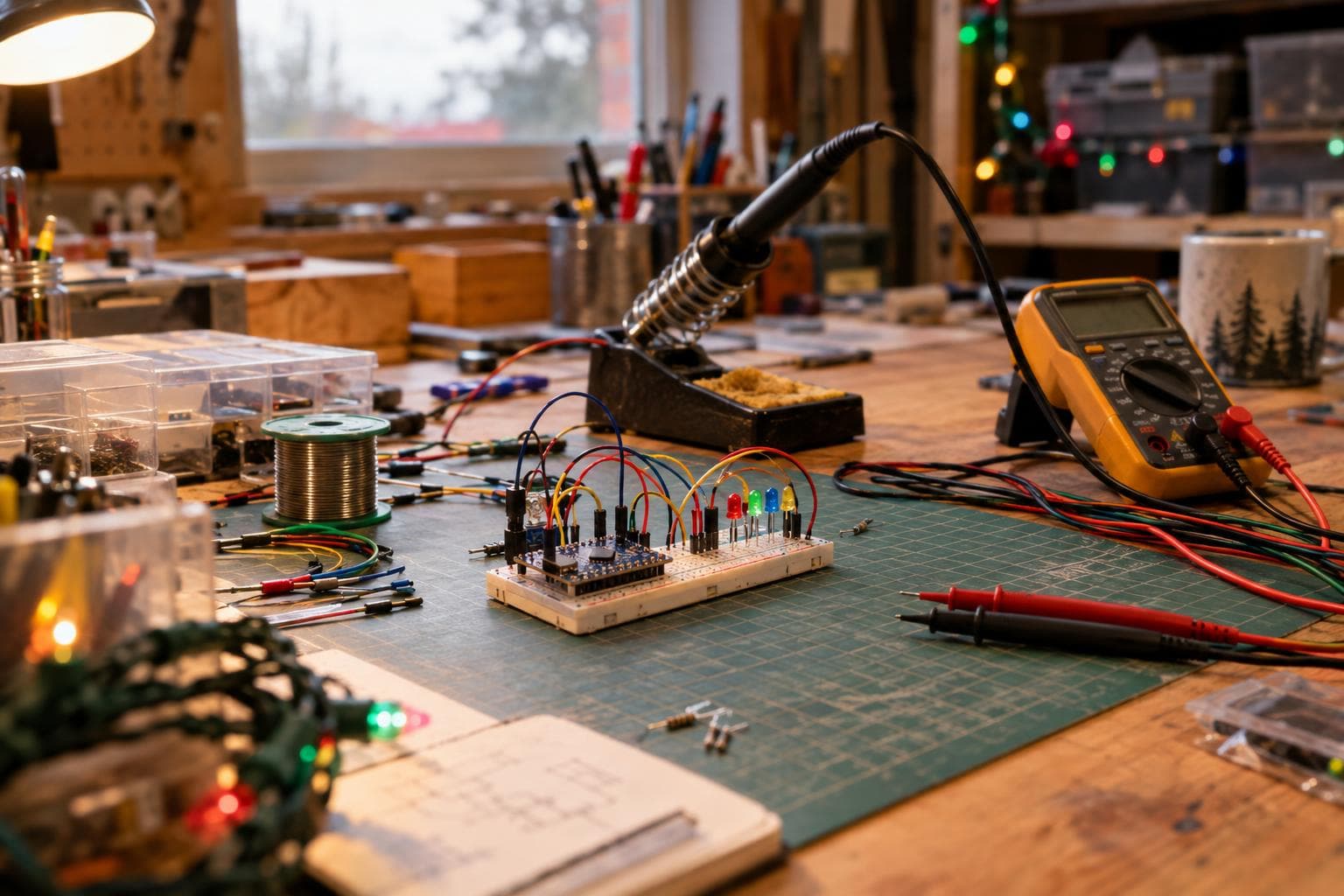
A holiday light controller rarely fails because the code cannot turn an output on. It fails because the builder counted fixtures instead of channels, sized the supply from average current, or left outdoor joints to tape and hope. Build the load map, wiring plan, and schedule months before the lights are needed, then test the assembled system under realistic load.
Start with the load, not the enclosure
Define a channel as one independently controlled output. A red, green, and blue strip with separate dimming needs three channels; a single-color strip needs one. An addressable pixel string may have one data channel while containing hundreds of separately controlled pixels, so channel count and power count are different calculations.
For each branch, record:
- the supply voltage
- the fixture type and length
- the maximum current, not the attractive idle figure
- the connector type at every break
- the fuse value and wire size
- the longest cable run from the supply
- whether the output is switched, dimmed, or digitally addressed
Add the branch currents at the worst credible scene. A controller with eight outputs rated at 5 A each does not automatically need a 40 A supply, but a full-white addressable display can approach its worst case even if most animations use less. The supply, fuse, MOSFET, connector, terminal, and cable each need a rating suitable for the actual branch current. The weakest item controls the safe limit.
Voltage drop deserves its own line on the worksheet. Cable resistance rises with length and falls with conductor area, and the load current changes the drop. Measure the voltage at the far fixture while the branch is at its worst scene rather than checking only the unloaded supply. A dim or color-shifted far end is often a distribution problem, not a software problem. For long pixel runs, power injection at planned points is usually a better fix than raising the supply voltage beyond what the pixels accept.
Our preferred first build is a low-voltage system with separate fused branches and a conservative supply. Extra capacity is useful for startup and future changes; an oversized controller is not useful if the connectors, cable, and enclosure were left at their original ratings.
| Architecture | Control granularity | Current calculation | Wiring burden | Main failure mode |
|---|---|---|---|---|
| Switched fixture branches | One state per branch | Sum each fixture's maximum current | Moderate, with one power pair per branch | A single branch fault takes out a fuse or output |
| PWM-dimmed constant-voltage strips | Brightness per strip or zone | Maximum strip current at full duty cycle | Higher, because voltage drop affects every run | Uneven brightness or a hot switching device |
| Addressable pixels | Individual pixel data, shared power topology | Pixel count multiplied by worst-case pixel current, plus controller draw | Highest, with data integrity and power injection | Brownout, corrupted data, or color errors at the far end |
| Sensor-triggered pathway lights | Zones or fixtures triggered by events | Idle draw plus simultaneous triggered load | Moderate, with sensor cable placement | False triggers or lights that never time out |
Five projects worth planning early
1. Fused low-voltage zone controller
Problem it solves: One timer or plug does not give useful control over roofline, trees, entryway, and display lighting. Separate zones let you keep a low-glare path light on while the decorative elements follow a different schedule.
Main parts and materials: Use a low-voltage DC supply, a microcontroller or programmable timer, one protected MOSFET output per dimmed DC branch, fuses, a suitably rated enclosure, terminal blocks, cable glands, and outdoor-rated low-voltage cable. A relay board can switch simple loads, but it is a poor choice for frequent dimming because a mechanical relay is an on-off device, not a PWM device.
The part harder than it looks: Heat and fault behavior inside the controller. A MOSFET with a low quoted on-resistance can still dissipate meaningful heat at several amps, and the datasheet value may assume a gate voltage your microcontroller does not provide. Check the resistance at the actual gate drive, calculate dissipation as current squared multiplied by resistance, and test the enclosure at the longest intended run. Put a fuse close to the supply feed and give each branch a fuse sized for its cable and load.
For a first outdoor LED control build, this is the project to pick. It teaches the load architecture without adding addressable timing, and the cheap approach is often good enough: ordinary single-color strings with switched zones are easier to diagnose than individually animated pixels.
2. Addressable pixel display with power injection
Problem it solves: A fixed-color controller cannot produce moving text, chasing patterns, or independent effects across a display. Addressable pixels place a small controller at each pixel, so data complexity and power complexity must be treated separately.
Main parts and materials: Plan for a controller with the required data protocol, a level shifter if the controller's logic level does not meet the pixel input specification, a suitable DC supply, injection feeds, fuses, bulk capacitance near the pixel power entry, data cable, signal conditioning where the controller documentation calls for it, and a weather-protected enclosure.
The part harder than it looks: Keeping data valid while the power distribution remains stable. A pixel chain can show random colors when the real fault is a voltage sag, a missing common ground, or a data line routed beside a noisy power conductor. Keep the data reference connected, follow the pixel manufacturer's voltage limits, and test a short segment before extending the chain. Inject power according to the measured far-end voltage and the pixel specification, not by copying a distance from someone else's installation.
Do not calculate supply size from the average animation. Use the maximum scene your firmware permits, then decide whether brightness limiting is a safety measure or only a visual preference. If firmware limits white output to reduce current, document that limit so a later code change does not silently overload the supply.
3. Astronomical entry and pathway controller
Problem it solves: A fixed clock schedule drifts relative to dusk. A motion sensor alone can leave a path dark until someone enters it, or keep it lit through the night after a false trigger.
Main parts and materials: Use a controller with a real-time clock or network time source, a location and timezone setting, an astronomical-schedule routine, a light sensor only if local conditions demand correction, a motion sensor with a defined timeout, and low-voltage outputs for the path and entry zones. Include a manual override that expires rather than becoming a permanent bypass.
The part harder than it looks: Defining the schedule around solar events and exceptions. A controller that computes sunset from date and location keeps a lighting schedule correct through the whole season without editing. It still needs the correct latitude, longitude, timezone, daylight-saving behavior, and clock recovery after a power loss. Decide whether the lights turn on at sunset, a fixed offset before sunset, or a civil-twilight event, then write those rules down. Add a late-night cutoff and a different rule for weekends or display nights rather than piling exceptions into unexplained conditionals.
An astronomical clock is the upgrade worth building here. A network dashboard is not, unless the installation actually needs remote changes; remote control adds credentials, update paths, and another failure mode to a system that may only need two solar calculations per day.
4. Weatherproof branch and connector test rig
Problem it solves: Decorative systems are often assembled in sections, so the connector plan determines whether the controller remains serviceable after rain, snow, and repeated setup.
Main parts and materials: Build a bench harness with the actual cable gauge, branch fuses, connectors, cable glands, strain relief, enclosure penetrations, and a representative fixture. Keep a multimeter, a current meter, and a load that can stand in for the real branch. For permanent joints, use sealed or potted connections suitable for the cable and environment.
The part harder than it looks: Protecting the joint from water movement, not just covering the visible seam. Outdoor low-voltage connections need sealed or potted joints, because a taped splice fails at the first freeze-thaw cycle. Water enters through capillary paths and damaged insulation, then the joint expands, contracts, and corrodes. A connector advertised as weather resistant still needs the correct cable diameter, assembly method, and strain relief. Test the complete joint, not just the connector body, and leave a service plan for replacing a failed branch.
This is the project most builders skip and the one that saves the most winter troubleshooting. A cheap sealed connector is good enough if its current, voltage, cable size, and environmental rating fit the job. Expensive connectors cannot compensate for water running down a cable into an enclosure, so orient cable entries downward and provide a drip path.
5. Seasonal display scheduler with removable scenes
Problem it solves: A display with several events needs repeatable scenes without rewriting firmware or leaving a laptop attached. It also needs a safe way to disable animations while leaving practical lighting available.
Main parts and materials: Use nonvolatile scene storage, a small display or button interface, a controller with enough timed outputs, a real-time clock or time synchronization method, a hardware enable switch, status indicators, and a versioned configuration file. Keep separate scenes for setup, normal operation, late-night operation, and fault state.
The part harder than it looks: Making configuration recoverable. Store channel names, maximum brightness, current limits, astronomical offsets, and timeout values in a format that can be inspected and restored. Validate values on boot so a corrupted setting cannot command full output indefinitely. A physical test mode should activate one branch at a time, with a timeout, instead of relying on a software screen that may be unavailable outdoors.
This is not worth building for four fixed-color strings and one daily on-off event. A labeled timer and fused junction box solve that smaller problem with fewer failure points. Build the scheduler only after the number of scenes, zones, and exceptions justifies it.
Make the wiring serviceable before winter
Draw the system as power paths and signal paths, not as a decorative layout. Mark the supply negative, controller ground, branch return, data reference, fuse location, and connector location. Use keyed or otherwise unmistakable connectors where a reversed branch could damage electronics. Label both ends of every cable; labels on the controller side alone stop being useful once sections are spread across a yard or display frame.
Keep signal wiring away from high-current switching paths where practical. Add strain relief before sealing a connection. Leave enough cable for one clean service loop, but do not coil excess cable into a warm enclosure. Protect unused outputs from accidental contact, and fit a master disconnect that removes power from the supply and controller.
Bench-test the complete chain in stages:
- run one branch at its maximum planned scene
- add branches while recording supply voltage and controller temperature
- test the farthest connector and the longest cable
- cut power and confirm the restart state is safe
- run the astronomical schedule across a simulated date change
- unplug one branch to verify the fuse and fault behavior
- operate the manual override, motion timeout, and late-night cutoff
Do this before attaching lights to a structure. A controller that passes a five-minute desk test has not yet demonstrated thermal behavior, voltage stability, or recovery from an intermittent outdoor connection.
Build the calendar backward from the first night
Start with the date the system must operate, then reserve time for the enclosure, wiring harness, firmware, fixture test, and a full-duration run. Do not leave connector selection until the lights are already mounted. The correct sequence is load inventory, channel map, power calculation, branch protection, enclosure layout, firmware schedule, bench test, weather test, installation, and a second full run.
Keep a written change record. If a string is replaced with a longer one, or a scene gains a white channel, update current, fuse, cable, and thermal notes together. Seasonal projects invite small substitutions that invalidate the original calculation.
A good holiday light controller is boring during operation. It turns on from the correct solar event, limits a fault to one branch, survives a restart, and leaves enough access to identify the failed part without dismantling the display. Building months early gives you time to prove those properties instead of discovering them in the weather.
Frequently asked questions
How many channels does my outdoor LED controller need?
Count every independently switched or dimmed load as one channel. For addressable pixels, count data outputs separately from pixels, then calculate current from the maximum pixel scene. Add a spare output only if the controller, fuse layout, and power supply can support the planned future branch.
Is an astronomical clock better than a light sensor?
For a seasonal schedule, yes. A controller that computes sunset from date and location stays aligned through the season without manual edits. A light sensor can correct for local shade or unusual weather, but it needs a clean mounting position and a threshold that does not chatter under passing headlights or snow cover.
Can I use taped splices on low-voltage outdoor lights?
No. Tape can hold insulation together, but it does not make a sealed joint through repeated wetting and freeze-thaw movement. Use a sealed or potted joint rated for the cable, current, voltage, and environment, then add strain relief so the joint is not carrying the cable's weight.
We build made-to-order holiday light controllers and outdoor LED control systems through Custom Electronics & Smart Systems, Design & Product Development, and Custom Projects.
Related services
All services →
Have a project in mind?
Tell us what you want built — we reply within 24–48 hours.