
- laser framing
- laser cutting
- machine setup
- maker mistakes
- job positioning
Laser Framing: Catch Job Setup Mistakes Before Cutting
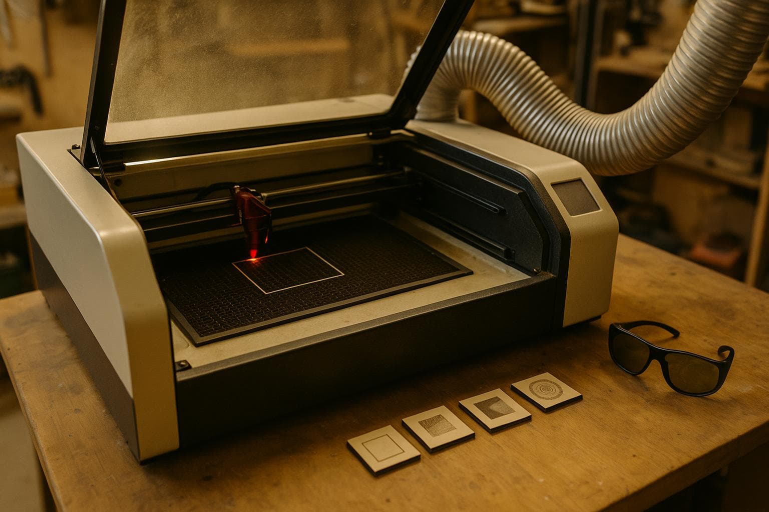
A laser job can be correct in software and still land in the wrong place, run off the stock, or clip a clamp. The fastest check is laser framing: run the job boundary with the beam disabled before committing material or machine time.
Mistake 1: Trusting the drawing instead of the material
A rectangle that measures correctly on screen says nothing about the sheet on the bed. Stock may be narrower than its nominal size, the edge may not be square, or the usable area may be smaller after trimming a damaged corner.
What it looks like after it lands
The first part is cut through the edge, an engraving is missing a corner, or the final pass leaves a section hanging over the material. If the job contains several pieces, the first few may fit while the last one runs out of room because the sheet was measured from the wrong edge.
The check that catches it
Place the material in its actual working position, then run the outline with the beam off. On a laser machine and software combination that supports framing, the head traces the bounding area of the job without firing the beam. Watch the head, not only the screen. The outline should stay over usable material at every corner.
This check takes about ten seconds on many setups. It confirms that the material is large enough for the planned placement. It also reveals whether the stock is sitting square to the machine axes. If the outline is inside the sheet at one end and close to the edge at the other, the material is rotated, the drawing is rotated, or the bed reference is not what you thought it was.
Do not confuse the bounding area with the visible artwork. A design can have empty space inside its overall rectangle, but the machine still has to travel through that rectangle. Framing the bounding area is the useful test because it checks the complete travel envelope of the job.
Mistake 2: Treating framing as a focus or settings test
Framing confirms placement, not focus or settings. The beam remains off during the outline, so framing cannot show whether the focal distance is correct, whether the chosen power and speed will mark the material, or whether the beam will cut through it.
What it looks like after it lands
The job is perfectly positioned but the mark is faint, too dark, incomplete, or wider than expected. A cut may score the top surface without separating the part, or it may leave excessive charring around the path. None of those outcomes contradicts a successful frame.
After framing, use the machine-specific focus method and a small test on the same material, finish, and thickness. A test strip or sacrificial corner is enough to compare the intended mark or cut. Settings move with material composition, coating, moisture, thickness, lens condition, air assist, and machine alignment, so a setting copied from a different sheet is only a starting point.
For cutting, test whether the part separates and inspect the edge. For engraving, inspect both the darkest detail and the lightest detail that must remain visible. If the material has a coated face, test that coating rather than an uncoated sample. Framing and testing answer different questions and should not be merged into one ritual.
| Check | What it proves | What it cannot prove | Failure caught |
|---|---|---|---|
| Beam-off frame | Job position and bounding-area clearance | Focus, power, speed, or cut depth | Artwork overhang, wrong origin, rotated stock |
| Focus check | Correct focal distance for the machine and material surface | Final contrast or complete separation | Soft engraving, inconsistent kerf, weak cut |
| Small test mark | A starting response from this material and setup | Performance across every part of a large sheet | Faint mark, excessive burn, poor contrast |
| Test cut | Whether the chosen process separates the test feature | Placement of the full job | Incomplete cut, fragile detail, excess charring |
Our position is firm here: do not buy a camera alignment system just to avoid a ten-second frame. A camera can help with printed artwork, irregular offcuts, or repeated registration, but it does not replace a material test and it does not fix bad focus. For a simple rectangle on a known sheet, the cheap check is good enough.
Mistake 3: Framing from the wrong origin
Laser software may position a job from a corner, the centre, or a stored machine origin. A preview job position can look reasonable while the actual origin is different from the one you used to place the material.
What it looks like after it lands
The design is shifted by a consistent amount, mirrored from the expected location, or placed near a different corner of the workpiece. This often happens after changing software, restoring a file, moving the head by hand, or switching between absolute and user-defined positioning modes.
Before firing, confirm three things:
- Which point in the design is being used as the anchor: corner, centre, or another reference.
- Which point on the machine or material is being used as the origin.
- Whether the software's preview job position matches the physical position of the head and stock.
Then frame the job from the same origin used for the cut. If the machine supports a pointer or visible position marker, use it as a placement aid, but trust the beam-off travel path for clearance. A pointer can be offset from the actual beam, and that offset must be known for the machine to be useful as a reference.
Mistake 4: Checking the outline but ignoring the workholding
A frame can fit inside the material while the machine head, nozzle, air-assist cone, or moving gantry still encounters a clamp, magnet, hold-down, raised edge, or warped section. The software only knows the path it was given. It does not know what you placed beside that path.
What it looks like after it lands
The head stops against a clamp, the material shifts during a cut, or the edge of the sheet lifts into the travel path. On a flat-bed machine, a small lift can change focus enough to spoil an engraving or prevent a clean cut. A frame also does not prove that every part of a warped sheet remains at the correct height.
Run the frame with all workholding installed. Keep fingers, loose scraps, magnets that can move, and temporary spacers out of the travel area. Watch the closest approach at each corner instead of assuming that a clear first side means the whole perimeter is clear.
For warped stock, framing is necessary but not sufficient. Flatten the material with a method appropriate to the machine, or choose stock that lies flat. If the machine has a movable gantry or head, account for the hardware around the beam, not only the beam position shown in software.
Mistake 5: Skipping the second frame after changing the file
A small edit can change the bounding area. Adding a border, changing text, converting strokes, increasing a margin, or rotating the design can move an otherwise safe job into an unsafe position.
What it looks like after it lands
The original file framed correctly, but the revised file clips the edge or collides with a hold-down. Another common failure is selecting one layer for the final run while framing a different selection, so the preview and the fired job do not describe the same travel area.
Save the file, verify the layers and output settings, and frame the exact selection that will run. If the software separates engraving and cutting into different passes, frame the combined job when possible. If separate framing is required, check each pass and the combined outer boundary.
Use this short pre-fire sequence:
- Confirm the material type, thickness, face, and usable dimensions.
- Confirm the origin and the job's preview position.
- Install clamps or other workholding and clear the travel path.
- Focus using the machine's normal method.
- Run the exact job boundary with the beam off.
- Run a small material test if the setting, stock, or finish has changed.
- Start the job only after the head path and test result agree with the plan.
The sequence is cheap because it uses information already available at the machine. It is also faster than diagnosing a bad cut after the sheet has been marked. Framing is the placement gate, not a substitute for focus, testing, or safe workholding.
Frequently asked questions
Does laser framing fire a weak beam?
On a machine and software setup whose framing command is designed as a beam-off outline, framing traces the job boundary without firing the laser. Confirm the machine's behavior in its manual or control panel before relying on it, because a visible pointer or preview light is not the cutting beam.
Does framing show whether the material will cut?
No. Framing confirms placement and clearance only. It does not confirm focus, power, speed, air assist, kerf, contrast, or penetration. Use a small test on matching material for those questions.
Why does my frame fit, but the cut still misses the stock?
Check the origin, the selected layers, the machine's beam or pointer offset, and whether the material moved after framing. Also check that the displayed job boundary matches the actual output boundary after strokes, offsets, and filled shapes were processed.
We build made-to-order laser-cut and engraved work through this request form.
Related services
All services →
Have a project in mind?
Tell us what you want built — we reply within 24–48 hours.