
- laser cutting
- laser test grid
- material test
- laser engraving
- maker tools
Laser Test Grid: Dial In Power and Speed
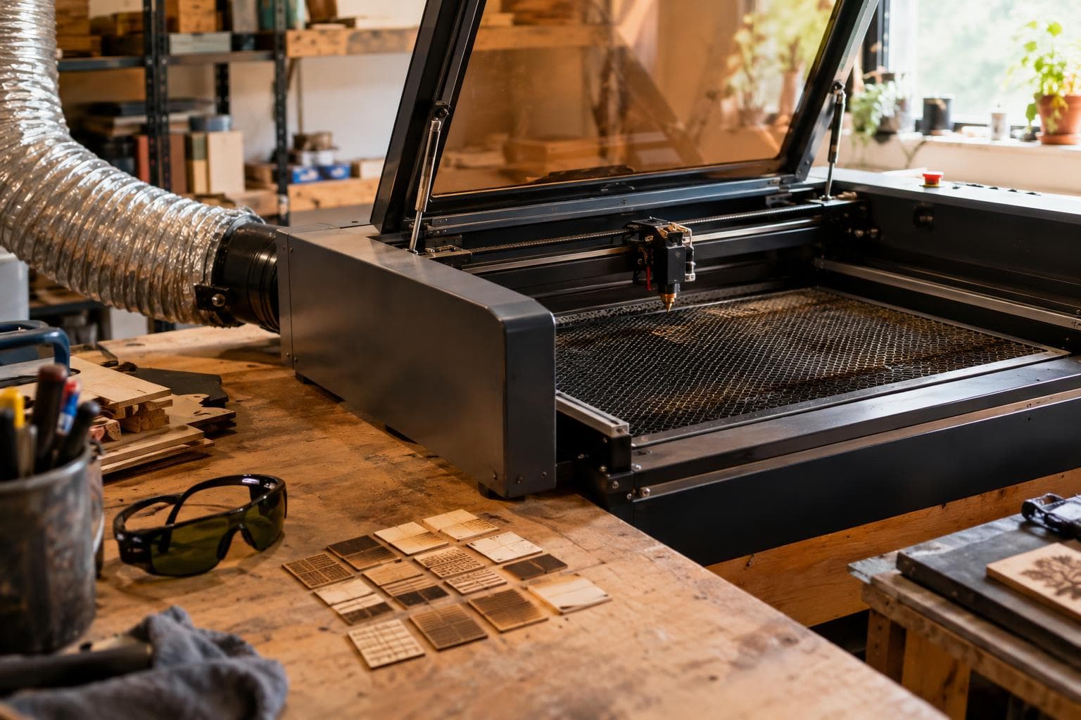
The right laser setting is not the number printed in a forum reply. It is the setting that produces the mark or cut you need on the sheet in front of you, with your tube, lens, air assist, focus, and material batch. A ten-minute laser test grid gives you that answer faster than comparing screenshots from another machine.
Why settings from another machine are only a starting point
A laser's percentage display is not a universal unit of optical power. A 60% command on one controller may not match 60% on another, even if both machines are described as 60-watt machines. Tube age, alignment, lens condition, focal length, air assist, exhaust, bed height, and the material itself all move the result.
The same material name also hides useful differences. Plywood species, adhesive, veneer thickness, cast versus extruded acrylic, coating, moisture, and surface colour all affect how the beam is absorbed and how heat leaves the cut. A setting from another machine is a starting point rather than an answer.
We use the lowest power and fastest speed that produce the required result, then verify the result at the edges and in the centre of the sheet. More power is not automatically better. It can widen a kerf, darken wood, melt acrylic edges, increase flare-up risk, and leave more residue.
Do not begin by changing hardware. A different lens will not correct a dirty lens, poor focus, a warped sheet, or a material batch that behaves differently. If the current lens is suitable for the thickness and detail you are cutting, the cheap way is good enough: clean it, set focus correctly, and run the material test before buying an upgrade.
Starting ranges for a power-and-speed grid
The table below is a starting reference for a clean-focus CO2 laser in roughly the 40–60 W class, using flat sheet and a controller that expresses power as a percentage. These are deliberately broad bands, not universal settings. They are most useful for laying out the first grid, not for skipping the grid.
| Job and starting material | Speed starting band | Power starting band | Passes | Main failure mode | Why the range moves |
|---|---|---|---|---|---|
| Engraving natural wood, shallow mark | about 150–300 mm/s | 12–30% | 1 | Pale mark or excessive charring | Move slower or raise power for a pale, dense grain; move faster or lower power for dark, soft wood and small text |
| Cutting 3 mm plywood | about 10–20 mm/s | 55–85% | 1 | Incomplete cut, wide kerf, or charred edge | Slower or higher power helps dense cores and adhesive; faster or lower power limits scorch on easy-cut stock |
| Cutting 3 mm cast acrylic | about 12–25 mm/s | 45–75% | 1 | Haze, melt, or incomplete separation | Slower or higher power helps tinted or dense sheet; faster or lower power protects small details from heat buildup |
| Cutting paper or card stock | about 25–60 mm/s | 15–35% | 1 | Flare-up, curled edge, or uncut fibres | Faster or lower power suits thin stock; slower only when the beam does not separate the fibres cleanly |
| Engraving coated sheet or painted surface | about 80–200 mm/s | 10–25% | 1 | Coating remains or base material is exposed too deeply | Lower power protects the substrate; slower power is needed for a coating that absorbs less energy |
A machine with a different wattage, a diode source, a different lens, or a different controller may need values outside these bands. Diode lasers also depend heavily on wavelength and the material's colour and coating. Do not copy the CO2 table to a diode machine as though the percentages were equivalent.
For a cut grid, hold the material, focus, air assist, and pass count constant while changing speed and power. For an engraving grid, hold the image, resolution, scan direction, and focus constant. If every square changes several variables at once, the test cannot tell you which adjustment caused the result.
Set up the material test so it answers a real question
Use a piece from the same batch of material as the job. The test has to run on the same batch of material as the job, not a sample saved from a different purchase or a scrap with a different veneer, coating, or core. Put the test near the sheet's edge only if that edge represents the usable sheet; some boards have more warp, glue, or damaged fibres there.
Before starting:
- Confirm the material is approved for your laser and does not contain PVC, vinyl, or another unsafe chlorine-bearing material. If the composition is unknown, do not put it under the beam.
- Clean the lens and mirrors according to the machine manufacturer's procedure. A dirty optical path can make a good setting look weak.
- Secure the sheet flat without placing clamps in the beam path. A change in focus across a bowed sheet can look like a power problem.
- Set the focus from the actual top surface. If the sheet thickness changes, the focal position changes with it.
- Use the normal exhaust and air-assist settings for the real job. Testing without them gives misleading smoke, heat, and edge results.
- Start with a small grid that fits in waste material, and label every square with its speed and power.
A cut grid should include short lines, a small square, an inside corner, and a hole close to the smallest feature the job needs. A long straight line can look successful while a corner still welds itself shut from heat. For engraving, include a filled patch, fine text, and a line or outline. A broad filled patch reveals density and scorching; fine text reveals whether the setting destroys small detail.
Use enough separation between test values to see a change. A grid from 14 to 15 mm/s may waste time if the material responds gradually and the machine's repeatability is lower than that difference. Begin with coarse steps, then run a smaller second grid around the best square.
Read the grid instead of chasing the darkest mark
For engraving, the darkest square is rarely the best square. Choose the one with the required contrast, clean edges, and acceptable texture. Wood grain can make a pale setting look uneven, while a high-power setting can look impressive but crush fine detail into a brown patch. On coated material, judge whether the coating is removed evenly without cutting into the substrate.
For cutting, check both the top and underside. A successful cut should separate with light pressure, leave an edge appropriate to the material, and preserve the required dimensions. Check these points:
- Measure a test slot and outside shape with the tool used for the real part. Kerf changes with focus, speed, power, material, and direction.
- Inspect inside corners. Excess heat rounds them and can make a press fit loose.
- Look for a strip of uncut fibre on the underside of plywood. That usually calls for a small speed reduction or power increase, but first rule out focus and warping.
- Check the back of acrylic for flare marks and residue. More power may finish the cut while making the visible face worse.
- Check small holes separately from large outside cuts. Heat has less time to leave a small feature.
- Keep the best square only if its edge and surface meet the job requirement, not because it is the fastest setting.
If the whole grid is weak, do not immediately raise power. Confirm that the beam is reaching the work, the material is at focus, the lens is clean, and the sheet is flat. If every square is overburned, confirm that the power command is being interpreted as expected and that the material is not thinner or more absorbent than assumed.
If one corner of the grid cuts and another does not, suspect focus variation, bed alignment, sheet warp, or beam alignment before changing the material setting. A power-and-speed grid cannot compensate for a focal plane that is not parallel to the work.
Dial in the final setting with a second test
Pick the best two or three squares from the first grid. Run a tighter grid around them on the same batch, using smaller changes in speed and power. Keep the final test feature set close to the real job. If the job contains small holes, test small holes. If it contains fine lettering, test the actual letter height and font style.
For a cut, add a dimensional check. Cut a known outside square and an inside opening, then measure both. If the outside dimension is correct but the opening is tight, the kerf or heat spread is affecting the inside feature. Adjust the drawing or compensate for kerf only after the machine and material combination has produced a repeatable cut.
For an engraving job, compare the test under the same lighting in which the finished piece will be judged. A setting that looks dark under a bright work light can look muddy under warmer room lighting. Record the chosen speed, power, focus offset, air assist, passes, material description, and date. The record is useful for the next sheet only as a starting point because a new batch can respond differently.
We would pick the cleanest result with the most margin, not the fastest square at the edge of failure. A cut that barely succeeds on a flat test can fail on a slightly bowed sheet. A mark that is just dark enough on one board can disappear into a darker section of the next board. A little margin is cheaper than discovering the limit on the finished part.
Do not buy a higher-wattage tube just because one material test is slow. If the machine cuts the required thickness cleanly, a new tube may add heat and change the settings without solving the actual problem. First prove that focus, alignment, air assist, exhaust, and material selection are not limiting the job. Buy an upgrade only for a capacity requirement your current setup cannot meet after those checks.
Frequently asked questions
How many squares should a laser test grid have?
Start with enough rows and columns to show a clear trend, often four to six speed values crossed with four to six power values. The exact count depends on how much waste material is available and how close the starting range is. A coarse first grid followed by a small focused grid usually gives more useful information than one very large grid with tiny setting changes.
Should I change power or speed first?
Change one axis at a time only when troubleshooting, but use both axes in the grid because they trade heat and exposure time differently. For a weak cut, verify focus and flatness first, then try a modestly slower speed before pushing power near the machine's limit. For a scorched engraving, a faster pass or lower power is usually preferable to adding another pass.
Can I reuse a laser setting from a previous sheet?
Reuse it as a starting point, not as proof. The test has to run on the same batch of material as the job because veneer, adhesive, coating, moisture, colour, and density can change the result. Keep the old setting in your notes, then confirm it with a small test on the new sheet.
The Boss Factory builds made-to-order laser cutting and engraving work; request a quote.
Related services
All services →
Have a project in mind?
Tell us what you want built — we reply within 24–48 hours.