
- laser cutting
- laser engraving
- corner burn
- min power max power
- laser troubleshooting
Laser Corner Burn: Why Corners Turn Darker
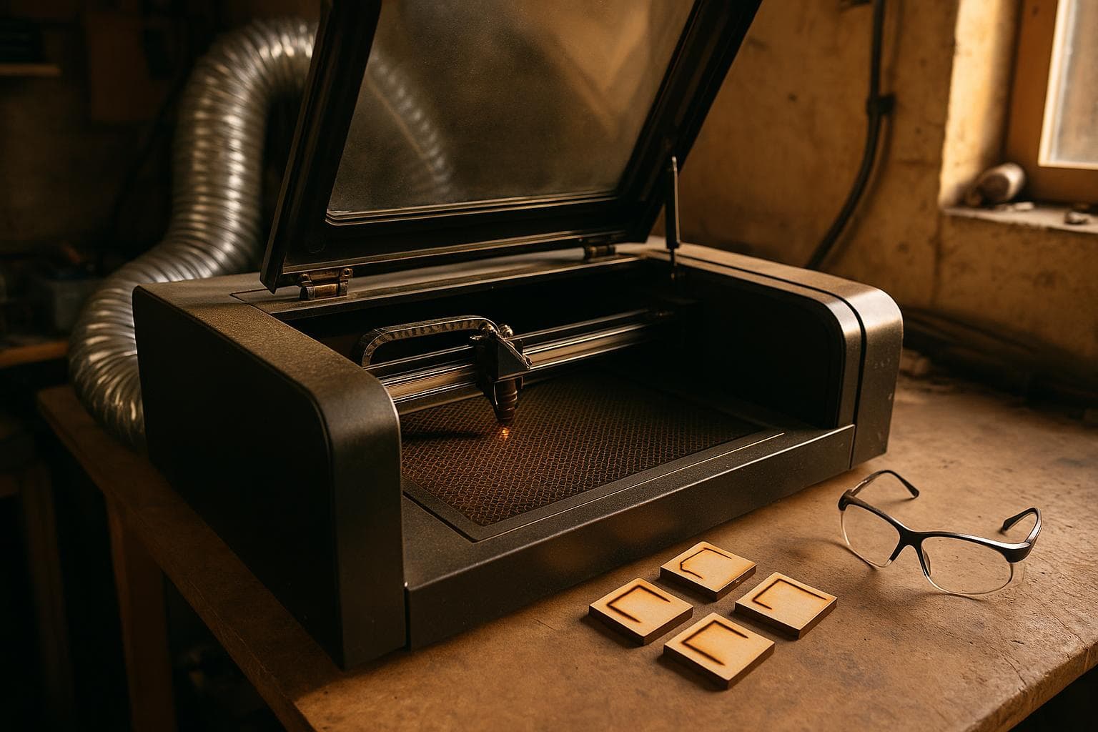
A straight laser line can look clean while every direction change turns brown, charred, or visibly wider. The short answer is that the head slows down for the corner while the beam keeps firing, so the material receives too much energy in too little distance.
The useful fix is power that tracks speed, not lower power across the entire job. Check the control settings first, then acceleration, focus, optics, material, and mechanics in that order.
How a laser corner gets extra energy
A moving head decelerates into a direction change and accelerates out of it. On a straight segment, it may travel at the programmed speed for most of the line. At a square corner, its speed drops, sometimes sharply, before it changes direction.
If laser output stays fixed while travel speed falls, the beam spends more time over each millimetre. The result is a darker mark, a wider kerf, or a small pit at the inside of the corner. This is laser corner burn, and it is a motion-and-energy problem before it is a lens problem.
For a constant material response, the useful relationship is:
energy per unit length ≈ power ÷ travel speed
Power that tracks speed keeps energy per unit length constant through a corner. The controller reduces output as the head slows, then raises it as the head accelerates. That approach preserves the straight-line mark instead of weakening every straight segment to protect a corner.
Power control, acceleration, and corner geometry
Start in the job software and controller settings. In software that exposes Min Power and Max Power, those values often control the low-speed and full-speed ends of a vector move. The exact behavior depends on the controller firmware and the software's device profile, so do not assume that a field with the same label behaves identically on every laser.
A common failure is setting minimum power equal to maximum power. That gives the controller no useful range for reducing output as speed falls. Another is setting minimum power too high. The corner may still burn even though the straight line looks correct.
Run a small test containing a square, a tight radius, and a straight line. Keep material, focus, air assist, and speed unchanged. Test several minimum-power values while leaving maximum power fixed. Use a scrap from the same sheet, and inspect both the corner darkness and the straight-line darkness.
Signs that the setting is the cause include:
- The burn changes noticeably as minimum power changes.
- Straight segments remain close to the same shade.
- Tight corners improve before broad curves do.
- The cut still completes at the chosen maximum power.
Do not lower maximum power first unless the straight sections are already too dark. Lowering power everywhere is the cheap workaround, and it is often good enough for a one-off engraving where a slight loss of contrast does not matter. For repeatable work, speed-scaled power is the better correction.
Some controllers expose dynamic power under a different name, and some machine classes do not support it during every motion mode. Confirm the controller manual and the generated motion commands before treating a software checkbox as proof that compensation is active.
A low acceleration setting makes the head spend longer slowing down and speeding up. A sharp internal corner gives it less distance over which to make that speed change. Both conditions increase exposure at the corner.
Do not raise acceleration blindly. The machine must be able to handle the change without skipped steps, vibration, frame movement, or visible ringing. A setting that makes a test square cleaner can still damage accuracy on a heavier head or an unstable frame.
A practical table for separating the patterns:
| Motion condition | Energy per unit length | Typical visible mark | Confirmation test |
|---|---|---|---|
| Constant power through slowdown | Rises as speed falls | Dark inside corner or enlarged kerf | Vary minimum power or enable verified dynamic power |
| Speed-scaled power with long deceleration | Closer to constant, but exposed longer | Mild corner darkening and possible overshoot | Compare acceleration settings within the machine's safe range |
| High power on straight segments | High at every speed | Lines and corners both too dark | Reduce maximum power on a scrap test |
| Tight geometry at normal control settings | Changes over a short distance | Small, sharp burn at direction changes | Compare square, radius, and straight paths |
For engraving, an overscan setting can reduce dark bands at the ends of raster passes, but overscan does not correct a vector corner. Keep those two problems separate.
Focus, optics, material, and air movement
Focus errors usually affect the whole design, but they can make corners look worse because a broad, weak spot encourages longer exposure. A dirty lens or mirror can also reduce power and spread the beam, leading someone to increase output until the corners char.
Before replacing an optic, inspect it under good light with the machine powered down. Look for smoke film, dust, chips, or a heat mark. Do not touch an optical surface with a dry cloth. Follow the optic manufacturer's cleaning method and use materials intended for that optic.
Confirm focus with a ramp test or the method specified for the machine. A flat sheet, warped plywood, or a workpiece held at the wrong height can shift the focal point enough to change kerf and edge color. Measure the actual work surface, not only the bed position.
The confirmation test is a focused straight-line grid at several power and speed combinations. If the narrowest, cleanest mark is not at the expected focus position, correct focus before changing corner compensation. If every position is broad or weak, inspect the optical path and verify that the lens is seated correctly.
Material variation can imitate a control problem. Wood density, resin pockets, adhesive layers, paint, masking tape, and surface contamination do not absorb or char at the same rate. A corner over a dense streak may look darker even with correct energy control.
Compare a corner on two clean areas of the same sheet. Then rotate the material and repeat the test. If the dark mark follows the grain, coating, or sheet location rather than the path geometry, machine settings are not the first suspect.
Air assist matters most during cutting and smoky engraving. A weak or misdirected stream can leave soot at corners because the head pauses locally and the smoke remains near the surface. Check the nozzle alignment, hose condition, and airflow path. Do not use airflow as a substitute for correct power scaling; excessive airflow can cool, move, or mark some thin materials.
For masked work, compare an unmasked scrap if the process permits it. Adhesive residue and masking type can alter the visible shade without changing the actual heat input. A clean edge on bare material and a dark edge through masking points to the masking process.
Mechanical motion and controller output
Mechanical faults are less common than incorrect power behavior, but they matter if the corner is dark on one side, doubled, displaced, or accompanied by ringing. Check belt tension, pulley grub screws, rail cleanliness, and head fasteners. With power removed, move the head through the working area and feel for tight spots.
A loose pulley can let the head hesitate or rebound at a direction change. A belt that is too loose can produce a soft, widened corner; one that is too tight can add friction and vibration. Correct tension is machine-specific, so use the manufacturer's adjustment method rather than copying a measurement from another frame.
The confirmation test is a low-power outline or a pen test, with the beam disabled if the machine permits it. Run the same square at different orientations and positions. A defect that follows the machine axis or repeats in one region suggests motion hardware. A defect that follows the vector geometry everywhere points back toward control settings or process exposure.
Only after these tests would we inspect controller output in detail. Compare the commanded speed and power behavior in the machine's preview, diagnostic output, or motion file where that format is documented. Do not edit machine commands by hand unless the controller documentation defines the relevant fields.
A repeatable dial-in procedure
Once the cause is identified, tune with a small matrix rather than a full-size project. Use the actual material and the same focus, airflow, masking, and path type.
- Choose the maximum power needed for the straight line or cut, not for the worst corner.
- Set a conservative minimum power, then increase it only until the corner shade matches the straight segment.
- Test a square, an acute angle, a radius, and a long line.
- Check both sides of the material for charring, incomplete cuts, or a raised edge.
- Save the settings with material thickness, focus position, path type, and controller profile.
For cutting, judge the result by complete separation and edge quality. For engraving, judge shade and line width. A setting that makes a sample look even can still fail if it leaves a cut partly attached, so inspect the actual process result rather than only the top surface.
The position we take is straightforward: fix speed-scaled power before chasing acceleration or buying optics. Lowering power everywhere is acceptable for a quick engraving or a material test, but it throws away useful energy on the straight sections and can create incomplete cuts. A new lens, faster controller, or heavier frame will not repair a missing power-control range.
Why do laser corners burn but curves look fine?
A curve may let the head change direction gradually, while a square corner demands a sharper deceleration and acceleration event. The tighter the radius and the longer the slowdown, the more likely fixed power is to overexpose the inside edge. Compare a square with a large-radius version at identical settings to confirm it.
Should I lower laser power or increase speed to stop corner burn?
First correct power scaling and check minimum power. If the straight line is already correct, lowering maximum power or increasing speed weakens the entire path. If both straight lines and corners are too dark, adjust overall exposure after confirming focus and material behavior.
What do min power and max power mean on a laser?
On controllers and software that support dynamic vector power, maximum power is generally the output target at the programmed travel speed, while minimum power is the lower output target during slower motion. Names and implementation vary by controller firmware and device profile, so verify the manual and test the values with a square and a straight line.
We build made-to-order laser-cut and engraved work through Laser Cutting & Engraving.
Related services
All services →
Have a project in mind?
Tell us what you want built — we reply within 24–48 hours.