
- 3d printing
- pause at height
- embedding magnets
- design for manufacture
- embedded hardware
Pause at Height Print: Embed Magnets, Nuts, and Sensors
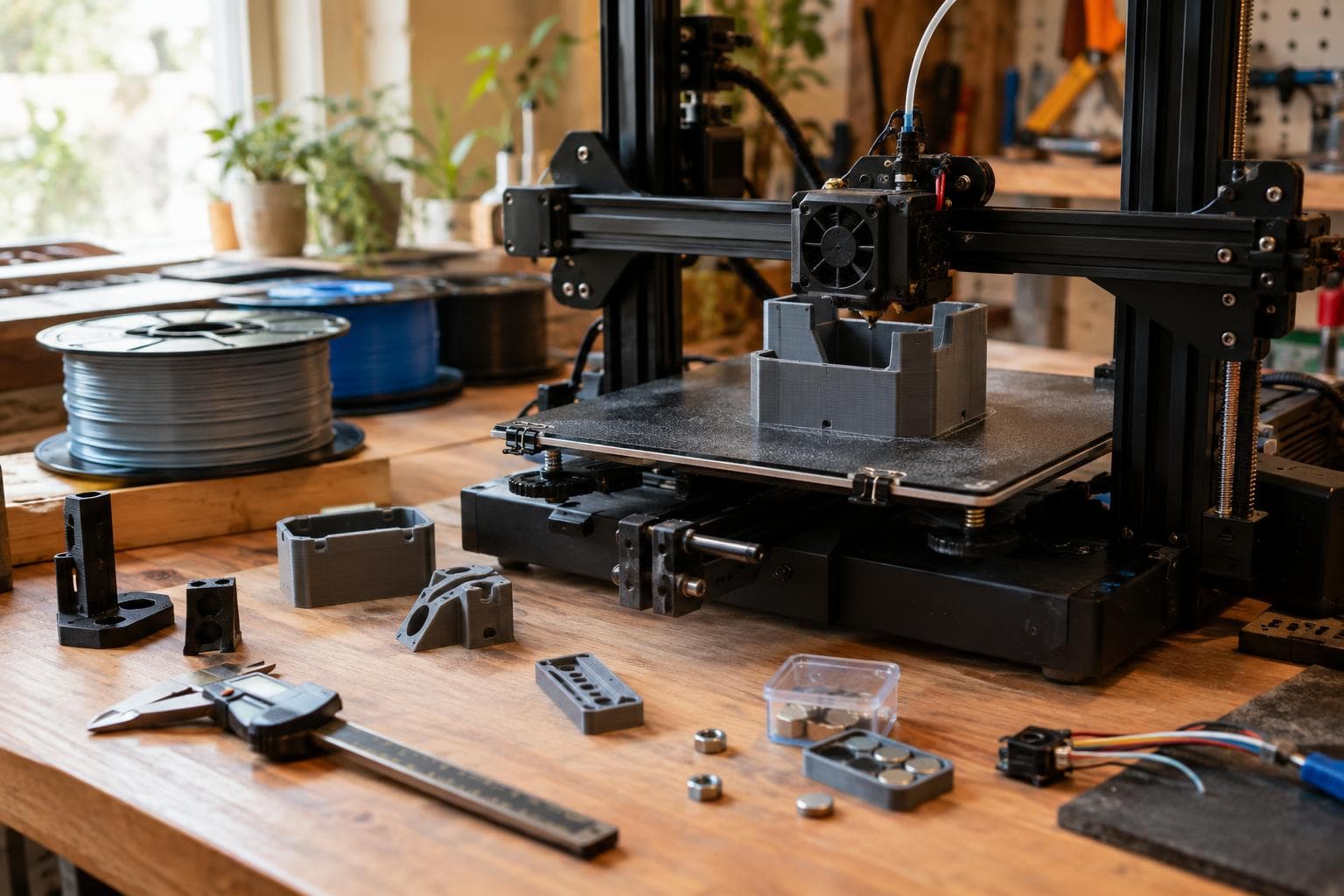
A pause at height print is useful only if the inserted part is lower than the next layer and the surrounding plastic can still bond. The short answer is to design a real pocket with clearance, a lead-in, and enough roof material, then treat the insert's temperature as part of the process rather than an afterthought.
Set the pause from the pocket geometry
The pause belongs after the printer has formed the floor of the pocket. In the slicer preview, find the layer that leaves the cavity open, then pause before the layer that will cover it. Do not select a Z height from the model's outside surface without checking the actual layer sequence; a change in layer height, elephant-foot compensation, or variable-layer setting can move the pause relative to the pocket.
The insert must sit fully below the next layer or the nozzle strikes it and knocks the print loose. That means the pocket depth must include both the insert thickness and a cover allowance. For a 0.2 mm layer height, a practical starting point is:
- Pocket depth equal to insert thickness plus 0.3 to 0.5 mm.
- At least one complete layer over the insert, with two or three layers preferred where the roof carries load.
- A flat pocket floor at least one layer thick, and thicker if the insert will be pulled out repeatedly.
For example, a 2 mm thick magnet should not sit in a 2 mm deep cavity. A 2.4 to 2.6 mm pocket gives the next layer somewhere to go and keeps the magnet below the nozzle's travel plane. The exact allowance depends on layer height, first-layer compensation, extrusion width, and how accurately the machine places Z. Preview the toolpath, then measure a test pocket before committing to a part with a hidden insert.
Give the insert a pocket the printer can make
A nominal CAD fit is not a printed fit. FDM walls have corner bulges, small holes often print undersize, and the first layer may spread into the pocket. We normally start with 0.2 mm radial clearance around a round insert on a calibrated machine, which gives 0.4 mm more diameter than the insert. If the printer leaves holes tight, move toward 0.3 or 0.4 mm radial clearance. A loose fit is easier to manage than a tight insert that sits proud of the layer plane.
For a hex nut, add roughly 0.2 to 0.4 mm to the across-flats dimension as a starting point. The lower end suits a well-tuned machine and a nut with consistent dimensions; the upper end is safer for a rougher printer or a nut with burrs. Add a small anti-rotation feature only where the load requires it. A hex pocket already resists rotation, while a round magnet needs a retention feature if the finished part will see shear or vibration.
The pocket entrance needs a lead-in. A 45-degree chamfer about 0.3 to 0.6 mm wide is enough for many small inserts. It removes the sharp edge that catches a magnet or nut and gives the insert a visual guide during the pause. Do not let the chamfer consume the roof thickness. For a sensor board or a wired module, use a wider funnel only at the entrance and keep the final pocket dimensions controlled below it.
Wire routing needs its own geometry. A channel should be deeper than the wire insulation and wider than the wire bundle, with rounded corners rather than a sharp notch. A channel that pinches the cable can pull the sensor out of position when the print resumes. Leave the cable exit on a wall that will not be crossed by the next nozzle path, and check the preview for travel moves through the opening.
Compare the insert before choosing the pocket
The insert's shape and thermal mass change the design more than most slicer settings. These are starting points, not universal tolerances.
| Insert | Clearance starting point | Thermal behaviour | Retention and strength | Common failure |
|---|---|---|---|---|
| Small neodymium magnet | 0.2 mm radial; increase if the hole prints tight | Metal pulls heat from the nearby melt and can be difficult to grip | Good pull force in the correct orientation; weak against peel if only buried shallowly | Magnet sits proud, flips during placement, or is installed with the wrong polarity |
| Brass or steel hex nut | 0.2 to 0.4 mm over across-flats | Usually a larger cold mass than a small magnet | Excellent resistance to rotation when the pocket matches the hex | Nut corner touches the next layer or the pocket traps a burr |
| Sensor board or wired module | Measure the actual board and add clearance for components and wires | Large boards remove heat over a broad area | Mechanical capture is better than relying on plastic fusion around electronics | Cable is pinched, board shifts, or heat damages the part |
For a nut, model the pocket around the across-flats measurement, not the corner-to-corner measurement. Add a small solid floor below it and enough roof above it that the fastener load spreads into several perimeter lines. If the nut will be tightened hard, a thicker wall or a captured metal washer outside the printed part may do more than adding infill. A pause does not turn plastic into a metal threaded boss.
For a sensor, check the component's temperature limits before putting it near a hot nozzle or warm polymer. A board may fit physically while its connector, battery, adhesive, or encapsulant does not tolerate the printing temperature. If the electronics cannot safely be present during the pause, use a removable cover or a separate mechanically retained cavity instead.
Solve the cold-insert adhesion problem
A cold insert pulls heat out of the surrounding plastic, which weakens layer bonding immediately around it. The effect is strongest with a metal nut, a broad sensor board, or any insert that has a large contact area compared with the volume of plastic around it. The next layer may look complete while the perimeter beside the insert has poor fusion.
The first choice is geometry, not a hotter profile. Keep the insert away from the external wall by several perimeter widths where the part allows it. Add material around the pocket, use a thicker roof, and keep the load path away from the cold boundary. Three 0.2 mm roof layers give 0.6 mm of cover, but a part that will be pulled or flexed may need a thicker solid section.
If the insert material permits it, bringing it closer to room temperature before placement reduces the immediate heat sink. Do not heat magnets, batteries, populated circuit boards, or adhesive-backed parts unless their manufacturer gives a safe temperature limit. A warm insert can also soften the pocket and make placement worse, so the useful temperature is the one that reduces the thermal shock without deforming the cavity or harming the component.
After placement, resume without unnecessary delay. The pause should be long enough to seat and orient the insert, not long enough for the part to become cold. Keep the insert level with a simple placement tool or a nonmagnetic pick when polarity matters. If the nozzle wipes across the pocket edge after resuming, reduce the chance of a snag by adding the lead-in and checking the first resumed travel move in the preview.
Do not increase nozzle temperature as the first response to every weak roof. Higher temperature may improve fusion but can also enlarge the pocket, soften the insert area, increase stringing, or damage electronics. A small test coupon with the same pocket, layer height, wall count, and pause is cheaper than tuning the entire model around a guessed setting. Pull-test the finished coupon and cut one open if the roof is safety-critical; the outside surface cannot show a weak bond around a buried part.
A pause-at-height test that earns its place
Before printing the final model, make a short coupon containing the actual pocket and cover. Use the same filament, layer height, nozzle, fan setting, and insert material. Test the features in this order:
- Confirm the pause occurs after the pocket floor and before the covering layer.
- Drop in the insert and check that its highest point remains below the next layer's planned top surface.
- Move the nozzle by hand with the motors disabled, or use a dry run above the part, to check that the nozzle cannot catch the insert.
- Resume and inspect the first two layers over the pocket for skipped lines, thin spots, or a raised roof.
- Break or cut the coupon to inspect the bond and check whether the insert moved during coverage.
If the insert is loose before the pause, reduce the clearance only after confirming the printer's dimensional error. If it is tight, increase the pocket size or improve the lead-in rather than forcing it in and damaging the floor. If the roof peels around the insert, enlarge the surrounding plastic, shorten the pause, or reduce the insert's thermal mass; changing infill alone rarely fixes a local cold boundary.
Frequently asked questions
How deep should a magnet pocket be for a 0.2 mm layer height?
Start with the magnet thickness plus 0.3 to 0.5 mm. That leaves the magnet below the next layer and gives the cover enough material to print. Confirm the result in the slicer preview and with a test coupon because first-layer compensation, extrusion width, and actual magnet thickness change the result.
Can I pause a print to add a sensor board?
Yes, if the board, connector, battery, and insulation can tolerate the surrounding print temperature and the pause duration. Leave clearance around components and wires, provide a cable channel, and use mechanical capture rather than expecting plastic to bond well against a cold board. A removable lid is safer when the electronics have uncertain temperature limits.
Why did the print crack around the embedded nut?
The nut acted as a cold heat sink and reduced layer bonding around its perimeter. It may also have left too little plastic between the pocket and the outside wall. Move the pocket inward, increase the wall and roof thickness, shorten the pause, and test the insert at a safer temperature if its material allows warming.
The Boss Factory builds made-to-order 3D printing, custom electronics, and design and product development work; request a quote.
Related services
All services →Have a project in mind?
Tell us what you want built — we reply within 24–48 hours.