
- power factor
- real power
- apparent power
- watt meter
- energy monitoring
Real vs Apparent Power: Why Clamp Meters Mislead
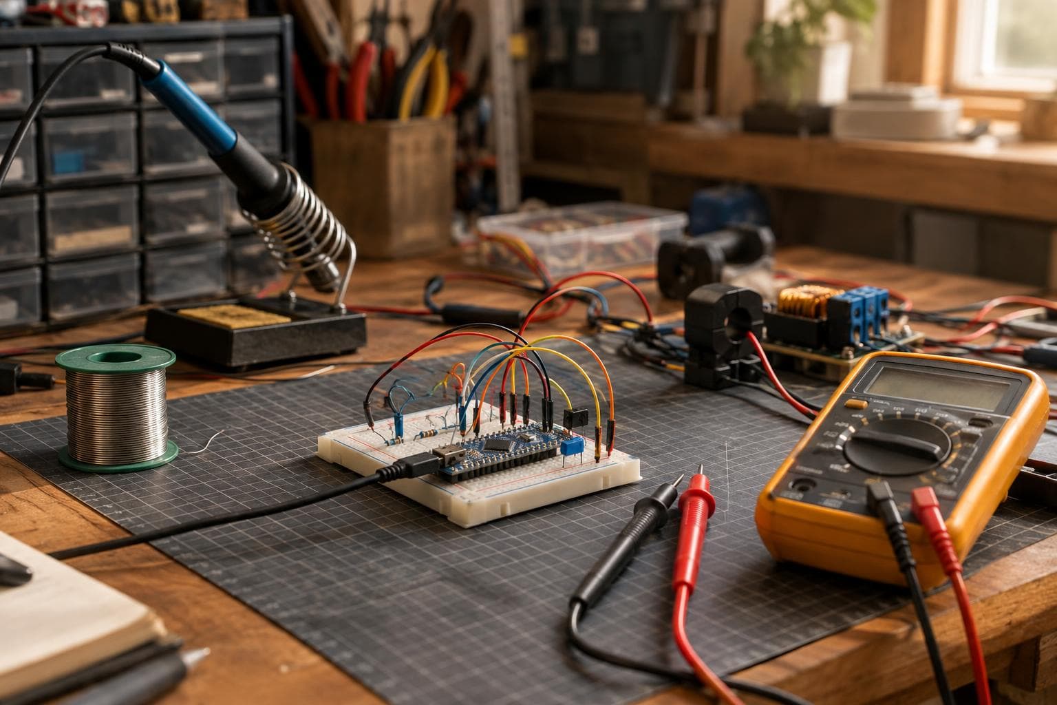
A clamp meter shows current, so multiplying that reading by nominal mains voltage looks like a quick power measurement. It is only an apparent-power estimate, and for motors or unfiltered switch-mode supplies it can overstate real consumption by a useful margin.
The clamp calculation stops at volt-amperes
The calculation is:
S = Vrms × Irms
Here, S is apparent power in volt-amperes (VA). A current clamp can provide Irms, and nominal mains voltage provides an assumed Vrms, but neither value tells you how voltage and current line up in time.
For a resistive load such as a heater, that shortcut is often close because current follows voltage and the power factor is near one. That is the grain of truth behind the claim. For a motor, transformer, or power supply with a rectifier and little input filtering, the relationship is different.
Real power is:
P = average(v(t) × i(t))
It is measured in watts. The multiplication happens on paired voltage and current samples, then the results are averaged over complete cycles. A meter that knows only current cannot calculate that quantity honestly.
The relationship is commonly written as:
PF = P / S
So a load drawing 6 A from a 230 V supply has an apparent power of about 1,380 VA. At a power factor of 0.65, its real power is about 897 W, before considering measurement error and voltage variation. The supply conductors still need to carry the current associated with the apparent power, which is why VA remains useful for wiring, transformers, breakers, and inverter capacity. It is not a substitute for watts on an energy bill.
Why motors and switch-mode supplies confuse the result
An induction motor draws magnetizing current as well as the current producing mechanical output. The current waveform can lag the voltage, particularly at light load, so its displacement power factor falls. Motor drives can improve the input waveform, but the result depends on the drive and its front end.
An unfiltered switch-mode supply creates a different problem. A bridge rectifier and reservoir capacitor pull current in short peaks near the voltage waveform peaks. The current may have the same general polarity as the voltage while still being badly distorted. That is distortion power factor, not just a phase angle.
Both cases make Vrms × Irms larger than average watts. The clamp is not necessarily wrong. It is answering a different question.
| Measurement approach | Input signals | Result for a motor | Result for an unfiltered switch-mode supply | Main failure mode |
|---|---|---|---|---|
| Clamp current × nominal voltage | Current only, plus assumed voltage | Overstates watts when power factor is below one | Overstates watts when current arrives in narrow peaks | Assumes voltage-current relationship that was never measured |
| Clamp plus measured RMS voltage | Separate RMS values, not synchronized products | Still reports VA, not watts | Still reports VA, not watts | RMS multiplication cannot reveal phase or waveform correlation |
| Watt meter using synchronized samples | Voltage and current sampled together | Reports average real power and power factor | Reports average real power, distortion effects included | Poor calibration, bandwidth, timing, or waveform handling |
What an honest watt measurement must sample
A real-power instrument needs a voltage measurement across the load and a current measurement through the load. It must sample both at known, matched instants. For each sample pair, it calculates instantaneous power, p[n] = v[n] × i[n], then averages enough samples to cover whole mains cycles.
That requirement has several practical consequences:
- The voltage channel needs suitable isolation and a known scale. A nominal 120 V or 230 V value is not a measurement of the actual waveform.
- The current channel needs its own calibration, whether it uses a shunt, current transformer, Hall sensor, or another sensor. A current transformer also needs correct burden, polarity, and phase compensation.
- The two channels need matched timing. A fixed delay between voltage and current samples creates a false phase shift, which is especially damaging for low-power-factor loads.
- The sampling bandwidth must preserve the parts of the waveform that carry meaningful power. An instrument that filters away current peaks can report a plausible but wrong result.
- The calculation must handle sign. Power returned to the supply is different from power consumed, and ignoring negative instantaneous power can inflate the average.
- The averaging window should not be so short that motor starting, compressor cycling, or power-supply control pulses dominate the displayed number.
For a microcontroller project, the cleanest validation is comparison against a known watt meter while testing a resistive load, a motor at more than one load point, and a switch-mode supply. Check voltage, current, watts, VA, and power factor separately. Agreement on current alone proves very little.
Pick the measurement that matches the decision
Our choice is direct: use apparent power when the decision concerns conductor or inverter capacity, and use measured real power when the decision concerns energy, heat, operating cost, or whether a machine is actually doing useful work.
A clamp estimate is good enough for a quick screening question such as whether a circuit is carrying several amps or whether a load is in the same order as a circuit limit. It is also the cheap option, and buying or building a synchronized watt meter for that narrow job is unnecessary.
Do not use it to estimate a machine's monthly energy consumption. Do not compare a motor and a heater by multiplying their clamp readings by the same nominal voltage. The motor may require similar current while converting less of that apparent power into average watts.
If the load is variable, log real power over time rather than taking one reading. A spindle, dust collector, compressor, or 3D printer can have startup, idle, loaded, and duty-cycle states that a single number hides. Energy is the time integral of real power, so the meter must keep accumulating watts, not just display a larger-looking VA figure.
Frequently asked questions
Can I calculate watts from a clamp meter?
Only for a load known to have a power factor close to one, and even then the result is an estimate. Current alone gives apparent power in VA. Real power in watts requires voltage and current samples taken together and multiplied sample by sample.
Why does my motor draw more amps than its watt rating suggests?
Its current includes reactive and waveform-related components that do not become average mechanical or heat-producing power. The motor's power factor may be well below one, especially at light load, so the apparent power in VA exceeds the real power in watts.
Does measuring RMS voltage and RMS current fix the problem?
No. Multiplying separately measured RMS values still gives apparent power. It does not capture phase displacement or current waveform distortion. The voltage and current waveforms must be sampled synchronously, then their instantaneous products must be averaged.
The Boss Factory builds custom electronics and smart systems to order through the quote page.
Related services
All services →
Have a project in mind?
Tell us what you want built — we reply within 24–48 hours.