
- cnc
- cam
- ramp entry
- helical plunge
- router bits
CNC Ramp Entry: Helical Plunge or Straight Plunge?

A router bit can cut sideways well and still enter a workpiece badly. At the exact centre of a rotating tool, cutting speed is zero, so the middle of a flat end mill does not behave like its outer edges during a straight plunge. The practical answer is to spread entry over distance: a ramped or helical entry converts a plunge into an angled cut.
Choose the entry method before generating toolpaths
Start in the CAM setup with the cutter, stock, workholding, and final depth already defined. Entry is not a cosmetic setting. It changes the load on the tool, the mark left on the wall, the time spent cutting air, and the chance of lifting a small workpiece.
For most pocketing and contouring with a router-style end mill, we choose a ramp or helix. A straight plunge is reserved for a centre-cutting tool, a cut where the tool manufacturer permits plunging, or a machine operation where the toolpath has a real reason to enter vertically. A drill is designed for axial cutting, but a typical two-flute or four-flute routing end mill is not automatically a drill just because it has a flat end.
The decision usually looks like this:
- Use a linear ramp when there is room for a long lead-in and the entry can stay outside a visible edge.
- Use a helical plunge when the pocket or hole has enough diameter for the cutter to circle without touching the finished wall too early.
- Use a straight plunge only after checking the cutter geometry and the material, not because the default CAM setting is convenient.
- Use a separate drilling operation for a true drilled hole when the hole size, depth, and tool support that operation.
A ramped entry travels horizontally while it descends. A helical entry does the same around a circular path. Both replace the concentrated axial load of a vertical move with an angled cutting path. They do not remove cutting load; they distribute it across more flute engagement and more toolpath length.
Set the ramp in Fusion 360 Manufacture
In Fusion 360, create or select the operation first, such as 2D Pocket, 2D Contour, or Adaptive Clearing. Set the tool, geometry, heights, and cutting passes before opening the Linking tab. The exact labels can move between Fusion 360 releases and operation types, but the relevant controls are generally under Linking and include Ramp Type, Ramp Angle, Maximum Ramp Stepdown, and, for helical choices, a diameter or radius control.
Set the bottom height and top height from the stock and model rather than typing an arbitrary total depth. Then set the ramp controls in this order:
1. Select the ramp type
Choose Ramp for a straight angled lead-in or Helix for a circular descent. Some operations expose a zig-zag or plunge option as well. Do not assume that selecting a ramp guarantees a ramp on every pass. The post-processor and available geometry still have to produce a legal move.
2. Set the angle or descent per revolution
A shallow ramp angle gives the tool more distance to remove the same depth, which lowers axial engagement but lengthens the operation. A steeper angle saves time and behaves more like a plunge. For a helix, the same idea is expressed as axial depth per revolution or a maximum ramp stepdown, depending on the operation.
The correct value depends on cutter diameter, flute count, stickout, material, chip load, machine rigidity, and whether the cut is inside a pocket or outside a profile. The tool maker's plunge guidance is the starting authority. If no plunge guidance is published, use a conservative ramp and inspect chips, sound, and deflection rather than borrowing a number from a different cutter.
3. Check the available run-in
A linear ramp needs a lead-in that fits without crossing the finished boundary. A helix needs enough clear diameter for the cutter centre to orbit. If neither fits, Fusion may shorten the ramp, add a plunge, or reject the operation depending on the geometry and settings.
Preview the toolpath in simulation with the stock visible. Look specifically at the first move into each pocket and at every island. A ramp that works for the first pocket may be impossible in a narrow slot.
Set feeds and speeds for the angled entry
The cutting speed at the exact centre of a rotating tool is zero, while the outer cutting edge has the highest surface speed. That is why a straight plunge with a flat end mill can rub or push material at its centre even while the perimeter appears sharp. A ramp lets the cutting edge engage through a moving, angled path, but the tool still needs a feed suitable for the material and cutter.
Keep the programmed feed consistent with the cutter manufacturer's chip-load method:
feed rate = chip load × number of flutes × spindle speed
That equation gives the lateral cutting feed. A CAM package may apply a separate plunge feed, ramp feed, or feed reduction. Treat those as different settings. A ramp is not permission to use the full side-cut feed for every material, especially if the ramp angle is steep or the cutter has a long unsupported stickout.
For a ramp, check these values in the operation's Cutting Data or Feed & Speed section:
- Spindle speed, based on the cutter diameter, material, and machine's usable range.
- Cutting feed, derived from the target chip load rather than copied from a different diameter tool.
- Ramp feed or plunge feed, reduced if the cutter maker calls for a lower axial-entry rate.
- Maximum ramp stepdown, limited so one revolution does not remove more depth than the tool and material can handle.
- Coolant, air, or chip evacuation, selected for the material and machine rather than assumed from the simulation.
If a ramp squeals, leaves dust instead of chips, or shows a polished rub mark at the entry, reduce heat first by checking chip load, chip evacuation, and ramp steepness. If the machine stalls or the workpiece shifts, reduce engagement and improve workholding before increasing spindle speed.
Compare entry methods by the problem they solve
| Entry method | Axial load | Space needed | Best use | Common failure mode |
|---|---|---|---|---|
| Straight plunge | Highest at entry, especially with a non-centre-cutting end mill | Very little | Centre-cutting tool or a permitted axial operation | Rubbing at the centre, deflection, broken flute, witness mark |
| Linear ramp | Spread over the ramp length | Lead-in distance outside or inside the boundary | Open contours and pockets with a usable lead-in | Ramp is shortened or becomes a plunge because geometry is too tight |
| Helical plunge | Spread around a circular path and over depth | Clear orbit diameter | Pockets, internal openings, and entries where a line cannot fit | Marks on the wall, insufficient diameter, or a helix that clips an island |
This table describes load behaviour, not a universal ranking. A shallow helix in a cramped pocket can be worse than a long linear ramp. A centre-cutting tool can tolerate a straight plunge that a standard router end mill cannot. The operation preview and the tool documentation decide the exception.
Verify the posted code and run the first cut safely
After post-processing, inspect the G-code or machine preview for the first descent. The controller may represent a ramp as coordinated X/Y/Z motion, while a helix may appear as circular interpolation with Z changing on each block. A post that does not support the intended arc format may linearize the helix or produce a controller alarm.
Do not confuse a machine's rapid move to the start point with a cutting plunge. The meaningful question is what happens after the tool reaches the programmed feed height. On a GRBL-style controller, a Z move governed by the configured plunge feed is still a plunge even if the CAM preview looked like a lead-in elsewhere.
Before cutting, verify:
- The tool is the one selected in CAM, including diameter, flute count, and stickout.
- The ramp begins in clear stock and does not cross a clamp, screw, or fixture.
- The entry does not start on a fragile corner or a small island.
- The first depth pass leaves enough material for the cutter to maintain a chip rather than rub.
- The machine's Z zero and safe height match the setup used in simulation.
- The post-processed file contains the expected XY movement during descent.
Make the first test in scrap or leave a small allowance on the real part. Watch the entry, not just the finished contour. A good ramp produces an ordinary cutting sound and chips that match the rest of the operation. A bad one announces itself through chatter, a stalled spindle, a pushed edge, or a visible ring at the start point.
Our default choice is a ramp or helix, not a straight plunge. The cheap way is good enough here: you do not need a special entry tool or a new machine to fix most entry problems. Correct geometry, a sensible ramp length, and feeds derived for the actual cutter usually solve them. Buy a centre-cutting tool only if your work repeatedly needs vertical entry and the added tool capability pays for itself; it does not fix a cramped toolpath, weak workholding, or a feed rate that is already wrong.
Frequently asked questions
Is a helical plunge better than a ramp for CNC pockets?
Usually, a helix is the better choice when a pocket has enough open diameter for the cutter to orbit. It avoids a long straight lead-in and spreads the entry around the tool. A linear ramp is better when the pocket is narrow or the lead-in can stay outside a visible edge. Check the simulated path for wall contact before choosing.
Can any end mill plunge straight down?
No. A tool must have geometry intended for axial cutting, and the manufacturer's data must permit the operation. Many routing end mills cut poorly at the exact centre because that point has zero cutting speed. A centre-cutting label helps, but it does not establish a safe feed for every material or depth.
Why did my CAM ramp still make a plunge mark?
The available lead-in may be too short, the helix diameter may not fit, or the operation may use a separate plunge move before the ramp begins. Inspect the simulated motion and posted code. Also check whether the selected operation exposes its ramp controls under Linking rather than under the main Cutting Data panel.
We build CNC & Precision Cutting and Design & Product Development work to order through our quote page.
Related services
All services →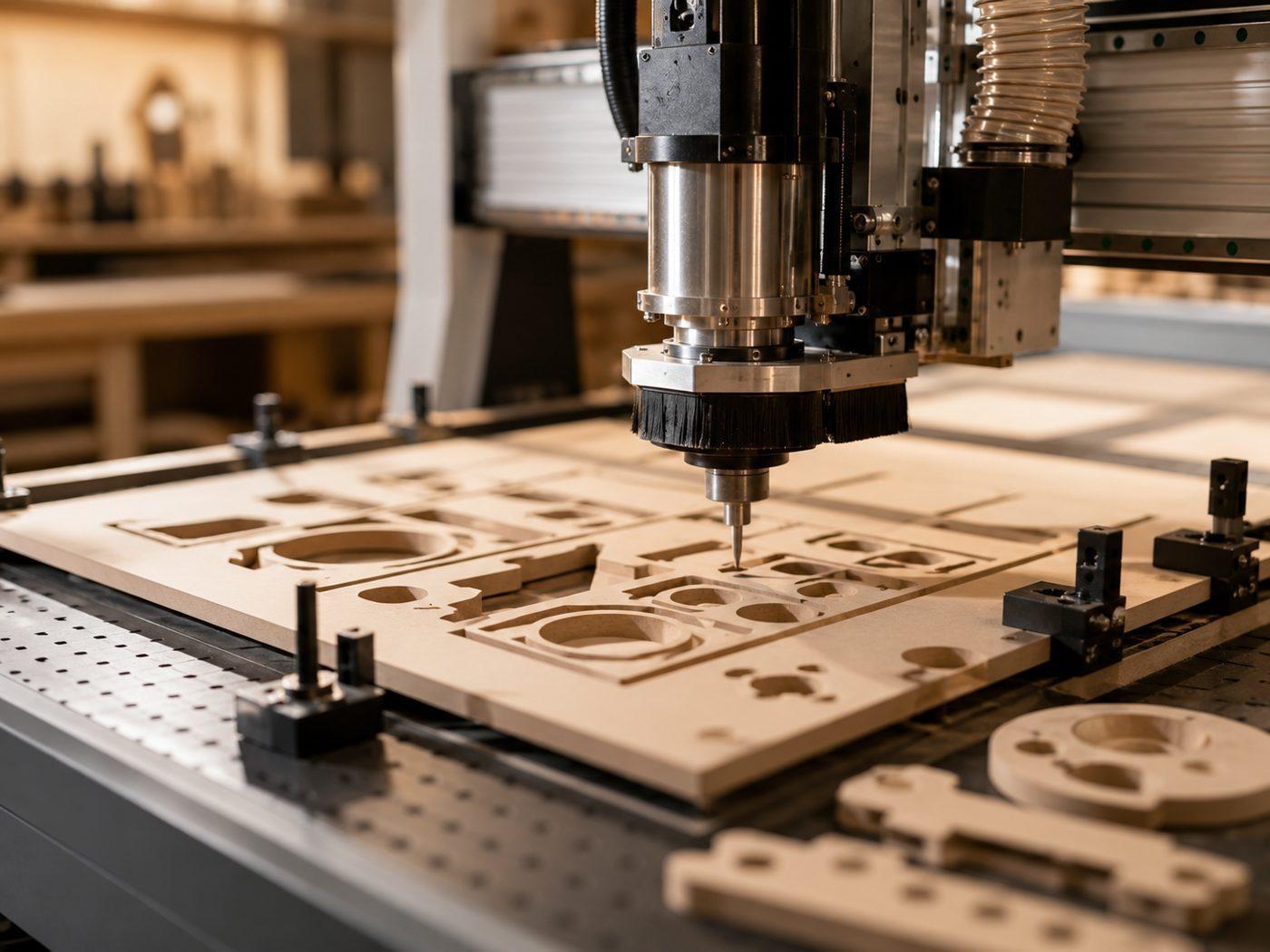
Have a project in mind?
Tell us what you want built — we reply within 24–48 hours.