
- 3d printing
- printed hinge
- living hinge
- fatigue
- pla
- tpu
Printed Hinge Fatigue: Why Layer Direction Decides Life
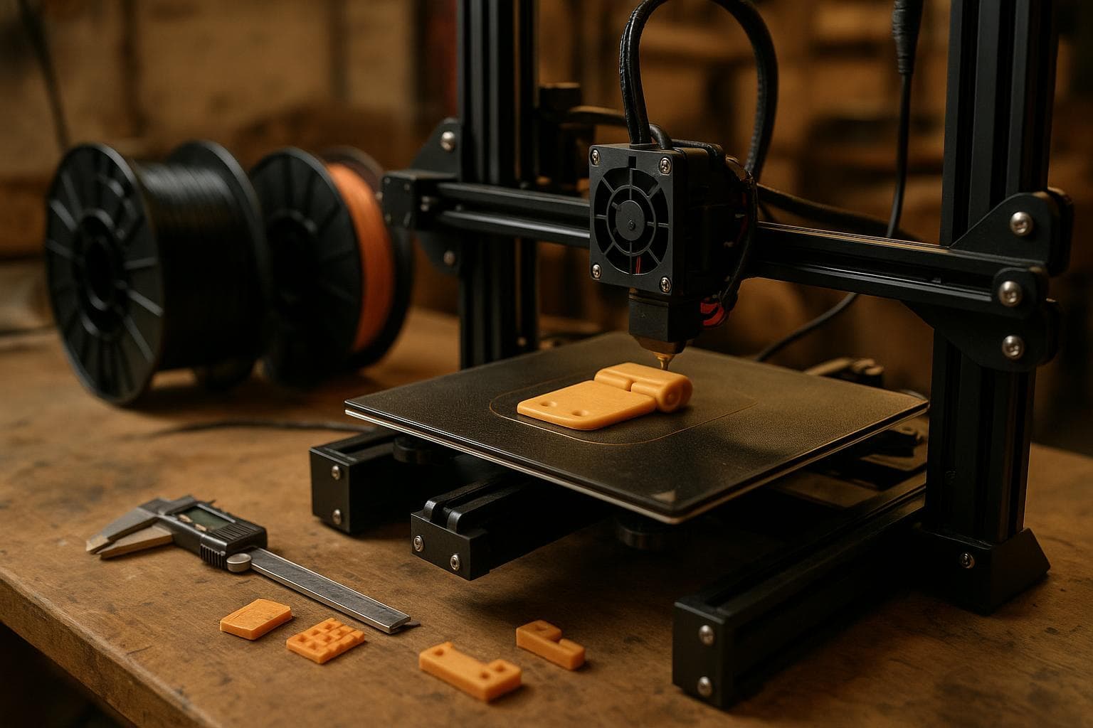
A printed hinge that works for two bends can still be a failed part. The real question is not whether the hinge moves on the first test, but whether its load path keeps repeating strain inside the material instead of peeling the print apart. The short answer is that orientation matters first, and PLA is usually the wrong choice for a thin flexing section.
Why a printed hinge fails in service
A hinge concentrates movement in a narrow line. That narrow line is a deliberate stress riser: the rest of the part stays relatively still while the web, knuckle, or thin strap takes nearly all of the rotation. Each cycle stretches one side of the section and compresses the other. The outer surface sees the largest strain, while the centre sees less movement.
That is fatigue. The part does not need to exceed its tensile strength in one event. A small crack can start at a layer boundary, a sharp corner, a void, or a surface notch. Each bend extends it a little farther. The hinge may feel normal until the crack has crossed enough of the section that the next bend finishes the break.
A printed hinge also carries a bending moment into the thicker material on either side. If the transition from the flexible web to the rigid body is abrupt, the strain piles up at that transition instead of spreading through a longer radius. A square shoulder is convenient in CAD but poor in service. Fillets help, though a very small fillet may disappear into the nozzle width and produce no meaningful change.
Do not judge a living hinge print by opening it once. Cycle it under the real angle, speed, temperature, and load. A hinge that survives unloaded bench testing may fail as soon as it carries a lid, resists a latch, or flexes while cold.
Layer direction decides the crack path
FDM parts are anisotropic. A deposited filament is usually stronger along its length than the bond between adjacent layers. The exact difference depends on polymer, nozzle temperature, cooling, extrusion, layer height, and the printer, but the weak direction remains a design concern.
A hinge that flexes across the layer boundary fails at the boundary, so the layers must run along the bend. Put another way, do not ask stacked layer interfaces to carry repeated peeling tension at the hinge line. Orient the part so the continuous deposited paths follow the hinge's bend and the repeated strain stays in filament paths rather than opening the interfaces between layers.
Print a small orientation test rather than committing to a full assembly. Make identical hinges in two orientations, keep the material and geometry fixed, and cycle them until one shows whitening, a crack, or a change in opening force. That test tells you more than a tensile-strength number because it reproduces the actual failure mode.
PLA is a poor fatigue choice for thin hinges
PLA is stiff, easy to print, and useful for checking fit. Those traits can make it look suitable for a hinge during assembly. In a thin flexing section, its poor fatigue resistance is the problem. Repeated strain produces cracking sooner than a material intended to tolerate flexing, especially if the hinge is thin, the bend angle is large, or the part operates cold.
PP and TPU do far better under repeated flexing than PLA. They are not interchangeable, though. PP is a strong choice for a thin living hinge when the printer can produce reliable first-layer and interlayer adhesion. Its low surface energy makes it difficult to print on many surfaces, and its shrinkage can distort a flat part. TPU is useful when the hinge needs a soft, compliant action, but its flexibility brings creep: a loaded hinge can remain partly deformed, and the response changes with temperature, thickness, and TPU hardness.
Nylon can also tolerate repeated movement well in suitable grades and orientations, but it absorbs moisture. Wet nylon can print with poor surface quality and inconsistent bonding, so drying and storage become part of the mechanical process. PETG is often a reasonable fit material, but it is not the usual first choice for a thin hinge that must cycle repeatedly. It can flex, yet its fatigue behaviour and creep under load are less attractive than PP or an appropriate TPU for this job.
| Material | Repeated-flex behaviour | Heat and moisture concern | Typical failure mode in a thin hinge |
|---|---|---|---|
| PLA | Poor fatigue resistance; good for fit checks | Softens under heat and becomes less forgiving when cold | Crack initiation at the web, layer boundary, or sharp transition |
| PP | Very good for living hinges when printed with sound adhesion | Shrinkage and difficult bed adhesion; service temperature depends on grade and load | Web tear or local crease after excessive angle or poor geometry |
| TPU | Very good flex life, with a softer response | Creep and temperature-dependent stiffness; hardness varies by grade | Permanent set, edge tear, or buckling under compression |
| Nylon | Often good fatigue performance in suitable grades | Moisture changes processing and mechanical behaviour | Interlayer weakness, abrasion, or crack growth after moisture-related print defects |
| PETG | Better suited to occasional flex than repeated hinge duty | Creep under sustained load; temperature response depends on grade | Crack or permanent deformation after repeated or held-open cycles |
Material choice does not repair a bad load path. PP printed with poor adhesion can fail earlier than a well-oriented prototype in another polymer. TPU can survive many bends but still fail if the web is pinched against a hard stop. Test the actual filament, not only the polymer name on the spool.
Design the hinge for strain, not appearance
The most useful design change is to make the flexible zone longer and thinner only within the limits of your material and print process. A short, thick web needs a small radius to reach the same rotation, so its surface strain rises quickly. A longer web spreads the same rotation over more length.
That does not mean making the web as thin as the slicer can draw. A section with gaps, under-extrusion, or uneven width has a notch at every defect. Start with a conservative geometry, then reduce thickness or increase length through test parts. Keep the bend angle below the point where the web folds against itself unless the material and shape are intended for that contact.
Use generous transitions into the rigid body. Add a radius on both sides of the web, remove sharp internal corners, and keep holes or cutouts away from the highest-strain area. If a pin or screw carries the alignment load, let it carry alignment. Do not make the flexible web act as both a bearing and a spring unless the section is designed for both jobs.
A hard stop is often worth adding. It prevents the user from bending the hinge farther than the test angle and makes the service condition repeatable. Leave clearance for the web to flex without rubbing on a neighbouring wall. Rubbing changes the load and can create a new notch at the edge.
The cheap solution is often good enough: if the hinge only opens during assembly or moves a few times per year, a PLA prototype or a separate mechanical hinge may be the sensible choice. Do not buy a specialised filament or redesign a whole enclosure for a hinge that has no meaningful cycle requirement. The upgrade matters when the part is opened daily, carries a spring or latch, or must remain functional after repeated handling.
Test the actual cycle before committing
Build the test around the way the part will be used. Record the opening angle, whether the hinge is loaded, and whether it is held open. A slow manual cycle can miss heat buildup and impact; a fast powered cycle can create a harsher test than normal use. Both may be useful, but they answer different questions.
Change one variable at a time. Compare orientation before changing wall count. Compare material before changing hinge length. If the hinge passes only when printed with extra walls, ask whether the added walls have moved the layer boundary or whether they have only shifted the crack to the edge. More material is not automatically more fatigue life; it can make the flexible area too stiff and move strain into a sharp transition.
For a part that matters, print several test pieces. Small differences in seam position, extrusion, cooling, and first-layer conditions can affect a fatigue result. The goal is not a universal cycle count. The goal is a design that keeps its strain below the level that your material, orientation, and process can repeat reliably.
Frequently asked questions
Should a living hinge be printed flat?
Often, but “flat” is not the design rule by itself. Print it so the continuous filament paths and layer arrangement carry the bend along the hinge rather than peeling at a layer boundary. Confirm the result in the slicer preview and with orientation samples.
Is TPU always better than PP for a printed hinge?
No. TPU is better when a soft, compliant hinge is useful and permanent set is acceptable. PP is usually the better pick for a thin, spring-like living hinge if your printer handles PP adhesion and shrinkage. The grade, hardness, geometry, and service temperature still matter.
Can PLA work for a printed hinge?
It can work for occasional movement, fit checks, or a hinge protected from repeated strain. PLA has poor fatigue resistance in a thin flexing section, so it is a poor default for daily cycling. If failure would be inconvenient, change the material and orientation rather than trusting a successful first bend.
The Boss Factory builds this kind of work to order through 3D Printing & Prototyping.
Related services
All services →
Have a project in mind?
Tell us what you want built — we reply within 24–48 hours.