
- servo jitter
- servo twitching
- hobby servos
- servo troubleshooting
- electronics
Servo Jitter: Four Causes and the Fix Order
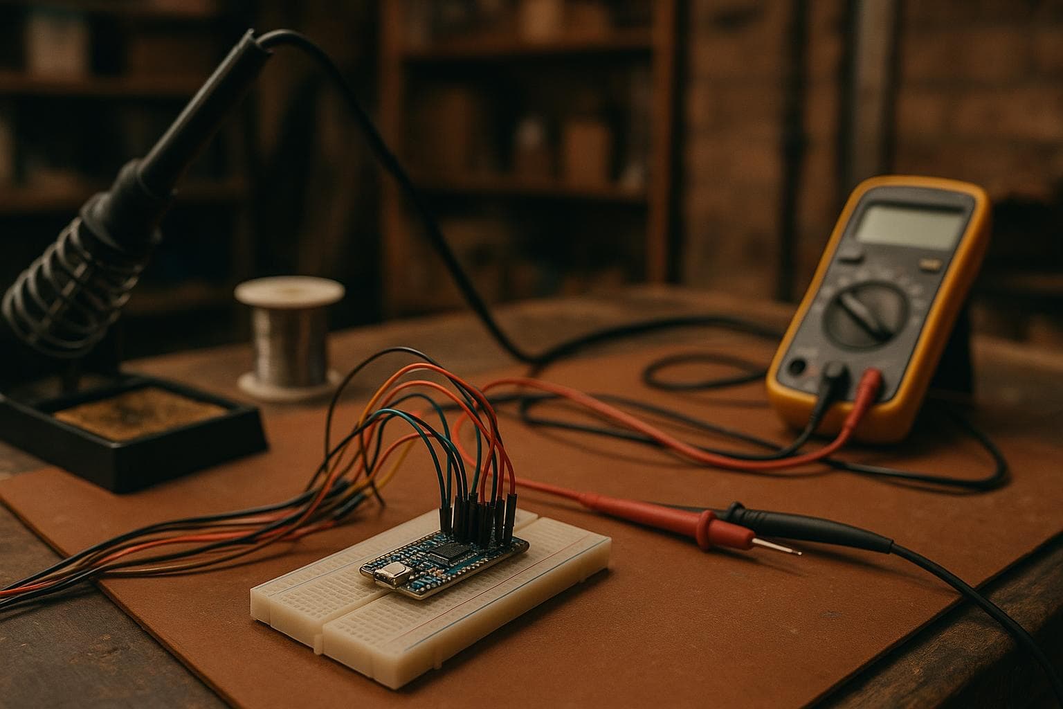
A servo that chatters, twitches, or drifts is often blamed on a bad servo. That is the last cause we check. Servo jitter usually starts in the power or timing around the servo, then moves into mechanical overload, and only then points to the potentiometer inside the case.
The useful question is not whether the horn moves. It is which part of the control loop is changing its mind. Work through the causes in this order, because each test removes a cheaper and more common fault before you replace a part.
What servo jitter means mechanically
A hobby servo reads position from a pulse whose width sets the commanded angle. The receiver or controller sends repeated pulses, and the servo compares the requested position with feedback from its internal potentiometer. It drives the motor until those two positions agree.
That makes pulse timing physical. If the pulse width changes from one frame to the next, the servo sees a changing position command and moves to follow it. A few microseconds can be visible on a lightly loaded horn, although the effect depends on the servo's electronics, deadband, gear train, and commanded angle range.
Do not confuse three different symptoms:
- Servo jitter: rapid, small movement around a target, often caused by power noise, pulse-width variation, or feedback noise.
- Servo twitching: an occasional jump, often caused by an interrupted signal, a poor ground connection, or code that briefly changes the command.
- Hunting: repeated movement past the target and back, often caused by load, backlash, an aggressive control loop, or a servo that cannot settle.
Start with the horn unloaded if the mechanism allows it. A servo that is quiet with no linkage attached but chatters in the machine has a load-path problem, not necessarily an electronic one.
Check the supply before changing code
A servo motor takes current in short bursts during startup, acceleration, and correction. The control board may report a normal voltage while the servo supply dips at the connector or at the servo's circuit board. Motor brushes and switching currents also put noise onto the same supply rail.
The supply path includes the regulator, wire, connectors, breadboard contacts, ground return, and any switch or fuse. A thin or long wire adds resistance. Under a current surge, that resistance creates a voltage drop. The servo then resets, loses feedback briefly, or receives a noisy reference, which appears as twitching.
Measure at the servo connector while the servo starts and while it pushes against a realistic load. A multimeter can reveal a large dip, but an oscilloscope is better for short transients. Probe across the servo's positive and ground pins, not only across the controller's supply pins.
Use a separate supply rail for the servo if the controller regulator is not rated for the servo's peak demand. Keep the grounds connected so the signal has a defined reference. Place bulk capacitance near the servo supply entry if the servo manufacturer permits it, but do not treat a capacitor as a substitute for an undersized regulator or a bad ground.
Our first design change is usually boring: shorten the high-current path, use a suitable wire gauge, replace loose connectors, and give the servo a supply with enough voltage and current margin. The cheap fix is often good enough here. A separate high-end controller does nothing for a supply that collapses at the servo.
| Cause | Electrical or mechanical change | Current or force clue | Useful test | Preventive change |
|---|---|---|---|---|
| Noisy or weak supply | Voltage dips or motor noise reaches the control circuit | Current rises during starts and corrections | Measure at the servo pins under load | Separate supply rail, sound ground, shorter high-current wiring |
| Unstable timing source | Pulse width changes between frames | Motor current may stay moderate | Observe the signal with an oscilloscope or logic analyzer | Hardware timer output and stable update code |
| Mechanical end stop | Motor remains in error because the target is unreachable | Heavy current, continuous buzzing, heat | Remove the linkage or reduce the commanded range | Set software limits inside the real travel |
| Worn potentiometer | Feedback voltage is noisy or discontinuous at certain angles | Current pulses as the loop hunts | Sweep slowly and watch feedback for dropouts | Replace the servo or its sensor if supported |
Verify the pulse timing source
Once the supply is clean, inspect the signal. A hobby servo does not receive an angle value directly. It receives pulse widths, commonly in a range around 1 to 2 milliseconds for many analog and digital hobby servos, but that range and the safe endpoints are not universal. Use the servo's documentation rather than assuming 1 ms and 2 ms are harmless limits.
The pulse must have a stable width. A software loop that turns a pin on, waits, and turns it off can be disturbed by interrupts, serial handling, display updates, or other tasks. The resulting pulse-width error is timing jitter, and the servo converts that error into movement.
A hardware timer output is the choice we prefer. It lets the peripheral generate the pulse while the processor handles other work. It does not cure every problem: changing timer prescalers, sharing a timer with another function, or updating the compare register at the wrong point in a cycle can still produce irregular pulses.
Check these points with a logic analyzer or oscilloscope:
- Pulse width at the servo connector, not only at the microcontroller pin.
- Repeat interval and whether a frame is occasionally skipped or shortened.
- Ground reference between controller and servo.
- Whether another library changes the timer or disables interrupts long enough to disturb the pulse.
- Whether the command value changes in software because of integer conversion, sensor noise, or a race between tasks.
Do not buy a more expensive servo to fix a pulse generated badly by code. For a light mechanism, the inexpensive timer peripheral already present in the microcontroller is usually sufficient. An external servo driver fixes a real pin-count, timing-isolation, or channel-count problem; it does not automatically improve a stable one-channel signal.
Find the mechanical end stop
Commanding a servo past its mechanical limit makes it fight the stop continuously, drawing heavy current and buzzing. The internal controller keeps seeing an error because the output shaft has not reached the requested position. The motor stays energized instead of settling.
The load path matters. Motor torque travels through the gears, output shaft, servo horn screw, linkage, bracket, and finally the stop in the mechanism. A hard stop concentrates force at the first small contact area. Repeated impacts can crack a printed arm, loosen a screw, strip a gear, or bend a thin bracket.
Heat follows the same path back into the servo. High current heats the motor, driver transistor, wiring, and connector. A servo that feels acceptable during a short bench test can overheat in service if it spends most of its time pressing against the stop. Moisture and dust make this worse by increasing friction, contaminating a linkage, or reaching a worn connector and feedback component.
Set the real limits with the linkage installed and the mechanism unloaded first. Move slowly toward each end while listening for buzzing and watching the current. Then test the expected load. Leave software limits inside the physical stops, with enough margin for assembly variation, backlash, temperature, and a slightly stiff joint.
The design change is to make the stop a position limit, not a torque reaction surface. If a physical stop is required for safety, place the commanded position short of it and make the stop broad, aligned, and capable of taking the occasional error without transmitting the full gear-train shock. Do not use a servo's advertised angle range as the available travel of your mechanism.
Test the internal potentiometer last
A hobby servo normally uses a potentiometer connected to the output shaft for position feedback. Its wiper and resistive track wear as the shaft moves. Vibration, dust, humidity, and condensation can add contamination or corrosion. A worn track often produces a noisy feedback voltage only at particular angles.
The symptom is position-dependent. The servo may be quiet near one end and twitch at the same middle position every time. Slow movement through that position can reveal a burst of hunting or a sudden jump. If the case can be opened without damaging the gear alignment, measure the feedback voltage while moving the output shaft slowly and steadily. The exact voltage span depends on the servo circuit, so look for discontinuities, noise, or dead spots rather than expecting one universal reading.
A loose horn, stripped gear, or output bearing with play can imitate a bad potentiometer. Check that the feedback shaft follows the output shaft without backlash before condemning the sensor. Also repeat the test with the signal source known to be stable and the supply measured at the servo.
If the potentiometer track is damaged, replacement may be practical only for a servo designed for service and with a matching part. On common low-cost servos, replacement is usually less reliable than replacing the servo. That is the unfashionable answer: do not rebuild a disposable unit unless the servo's mounting, calibration, or unusual form factor makes the work worthwhile.
A fault-finding sequence that saves parts
Use this order at the bench:
- Remove the mechanical load and confirm the horn is not hitting a stop.
- Power the servo from a supply suited to its peak demand and measure voltage at its connector during movement.
- Confirm a shared ground and inspect every high-current connector.
- Capture the control pulse and check width, repeat interval, and interruptions.
- Reconnect the linkage, set limits below the stops, and test the expected load for several minutes.
- If the fault follows one shaft angle with clean power and timing, inspect the feedback potentiometer and gear train.
This order follows the failure energy. Supply faults disturb the electronics, timing faults change the command, end stops turn correction into heat and force, and sensor wear corrupts feedback. Replacing the servo first can hide the root cause and leave the next one damaged in the same way.
Can a capacitor stop servo jitter?
Sometimes, if the problem is a brief supply dip close to the servo. It will not correct a weak regulator, a poor ground, unstable pulse timing, a binding linkage, or a worn potentiometer. Measure the supply during motion before choosing a capacitor value or assuming the capacitor fixed the fault.
Does a higher refresh rate make a servo smoother?
Not automatically. The servo's input circuit determines which pulse intervals it accepts, and some analog servos expect a conventional repeating frame while some digital servos accept faster updates. Use the manufacturer's specified range. A faster update rate can expose timer conflicts or overload a controller without reducing pulse-width jitter.
How far inside the mechanical stop should the software limit be?
There is no universal angle or percentage. Establish the stop with the actual horn, linkage, load, and assembly tolerances, then back the commanded limit away until the servo settles without buzzing at the worst expected condition. Verify both ends after the mechanism warms up and after any linkage adjustment.
The Boss Factory builds servo-control fixtures and related custom electronics to order through Custom Electronics & Smart Systems and Custom Projects.
Related services
All services →
Have a project in mind?
Tell us what you want built — we reply within 24–48 hours.