
- z banding
- z wobble
- 3d printing
- failure analysis
- leadscrew
Z Banding: Read Regular Bands Before Changing Settings
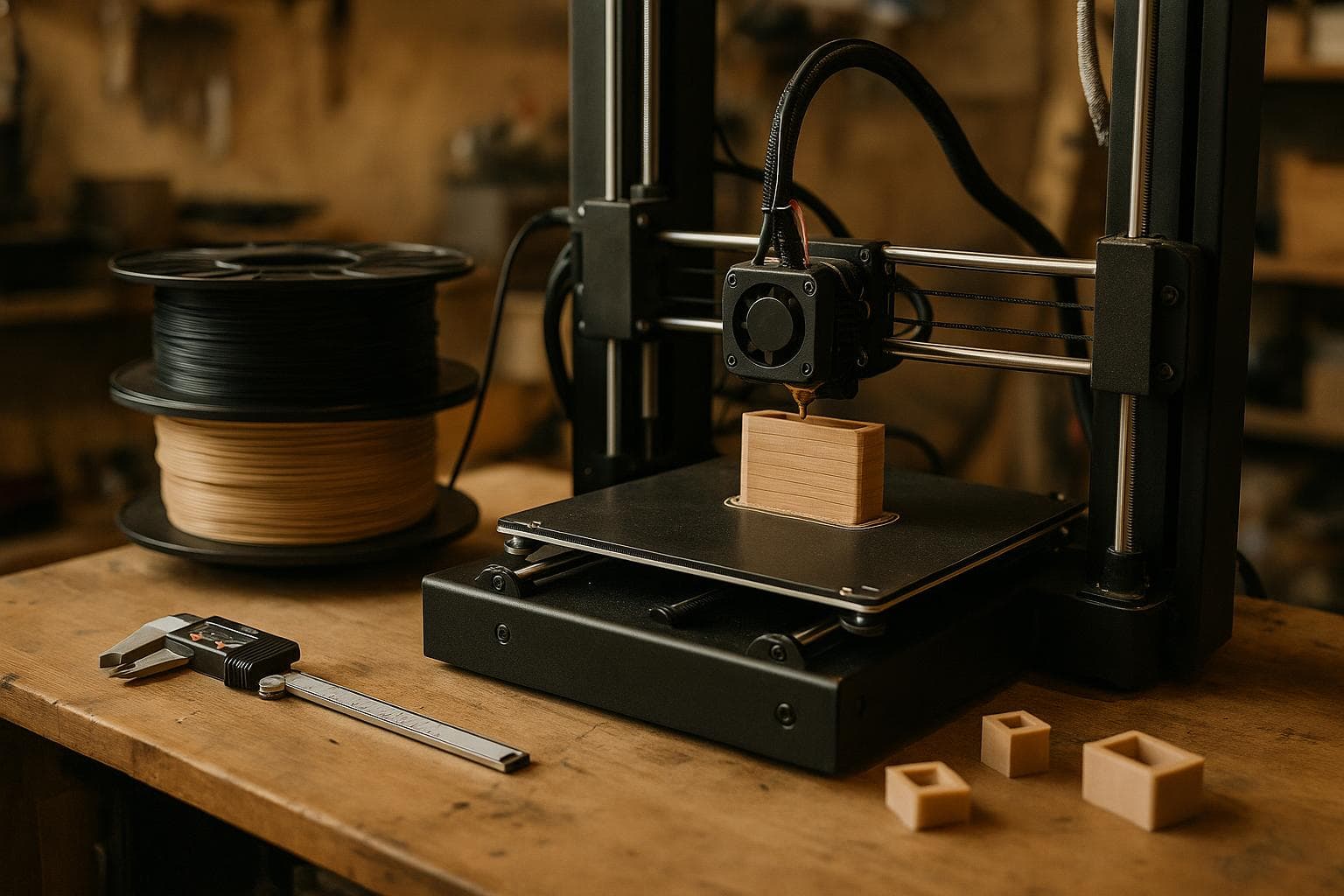
Regular horizontal bands on a part are not automatically an extrusion problem. The useful question is whether the distance from band to band matches the layer-height pattern or a mechanical period in the Z axis. Measure that spacing first: calipers narrow the cause faster than changing settings at random.
Why regular z banding fails in service
A band is a surface symptom, but the service failure starts in the load path. A repeating ridge and valley changes the local wall thickness and can leave a sharp transition where a smooth surface was intended. Under a static load, that may only affect fit or appearance. Under repeated bending, vibration, or clamp pressure, each valley can act as a small stress riser.
Printed parts add another weakness. Their strength is directional because adjacent roads and layers do not behave like a continuous, isotropic material. A wall loaded across its layer interfaces can open along those interfaces, while a wall loaded along the roads may carry the same force with less separation. A regular height error can make that difference worse by concentrating load at the same vertical positions.
Heat and moisture can turn a marginal part into a failed one. Repeated heating and cooling changes dimensions and can drive fatigue at an already uneven surface. Moisture-sensitive filaments such as nylon absorb water and can swell or lose mechanical performance; the amount depends on resin, exposure, and conditioning. PLA, PETG, ABS, ASA, nylon, and filled grades also differ in creep and softening, so a band that survives a room-temperature bracket may become a problem near a heat source or under a constant load.
That is why polishing, filler, or a thicker perimeter is not the first answer. If the bands mark a cyclic movement in the machine, the same error can remain inside the part after the surface looks better.
Use band spacing to separate the causes
Measure vertically from the center of one band to the center of the next at several points. Use calipers on a section with clear peaks or valleys, and record the average rather than trusting one interval. Measuring the band spacing with calipers narrows the cause faster than changing settings because the spacing is a fingerprint of the process.
The first comparison is against the layer height and its repeating pattern. If the slicer uses a constant layer height, a defect that appears on every layer will be separated by that layer height, not by a much larger mechanical pitch. If the slicer uses variable layer height, the marks may follow a sequence of layers, so add the heights in that sequence and compare the sum with the measured band interval.
The second comparison is against the Z-axis mechanics. If the bands are spaced at the leadscrew pitch, the fault points at the Z axis rather than at extrusion. A leadscrew with a 2 mm pitch, for example, advances 2 mm per revolution, so a periodic error tied to one revolution can produce bands about 2 mm apart. That does not prove the screw is bent. Coupling misalignment, a tight nut, a damaged nut, a thrust-bearing issue, or a frame that is not square can all turn screw rotation into height variation.
Do not confuse pitch with lead on a multi-start screw. Lead is the axial travel per revolution; pitch is the distance between adjacent threads. A single-start screw has equal pitch and lead. A multi-start screw does not, so identify the actual screw and its lead before matching a measured band interval to the motion.
| Likely source | Band spacing or pattern | Useful confirmation | Main service risk | First correction |
|---|---|---|---|---|
| Leadscrew-periodic Z error | Close to one screw lead or a simple fraction of it | Measure screw lead, then compare several band intervals | Repeated height error and local stress concentration | Inspect alignment, coupling, nut preload, and bearings |
| Layer-height sequence | Equal to one layer or the sum of a repeating layer sequence | Review slicer layer data and compare against the part | Dimensional variation between layers | Test constant layer height and inspect the resulting pattern |
| Extrusion flow variation | Often follows feature changes, pressure cycles, or line width rather than fixed height | Print a wall and compare bands with speed, retraction, and flow events | Voids, weak road contact, and uneven wall thickness | Check filament condition, drive feed, nozzle, and pressure control |
| Frame or gantry movement | Spacing may vary with height or appear as a broad wave | Check squareness, rollers, rails, and motion under power-off load | Misalignment, binding, and progressive wear | Remove preload and correct the mechanical geometry |
A band interval that stays fixed in millimetres across several parts is more suspicious for machine motion than for random extrusion. A defect that moves when layer height changes deserves a slicer or extrusion investigation. A defect that stays at the same Z heights on every print deserves a frame, screw, or gantry check.
Tests that isolate Z-axis banding
Start with a simple tall wall or rectangular tower using the same material and nozzle. Avoid a complex part that hides the period inside corners, infill changes, and cooling events. Record the layer height, line width, material batch, and orientation.
Run these checks in order:
- Mark the band centers and measure at least five intervals near the lower, middle, and upper sections.
- Measure the lead of the Z screw or obtain it from the screw specification. Do not infer lead from the apparent band alone.
- Rotate the screw by hand with power removed and watch for lateral runout, tight spots, or a nut that changes resistance through one revolution.
- Check whether the coupling allows the motor shaft to force the screw sideways. A coupling must accommodate small angular error without pulling the screw out of line.
- Confirm that the gantry rises freely with the motors disabled. Binding can make a periodic screw error much more visible.
- Print a second tower with a different layer height. A band pattern that scales with the layer sequence is not behaving like a fixed screw-pitch error.
- Inspect a thin wall for under-extrusion, gaps, and changes in line width. A caliper reading of the finished wall is useful, but it does not replace visual inspection of the roads.
The cheap test is good enough here. A caliper, a known layer-height file, and a careful power-off motion check usually tell more than a replacement lead screw bought before the spacing is measured. A Z-wobble upgrade does not fix an extrusion problem, and a new nozzle does not correct a misaligned screw.
Correct the cause, then change the part
If the spacing matches the Z lead, correct the motion system before tuning flow. Check the screw for straightness, but do not replace it as the first move. Verify that the screw is not being used to locate the gantry laterally, that the nut is not over-constrained, and that the coupling is not forcing angular error into the assembly. Set preload only as far as needed to remove play. Excess preload creates binding and can worsen the pattern.
If the spacing follows layer height or a variable-height sequence, review the slicer path and extrusion system. Dry the filament when its material requires it, check the drive gear and idler pressure, clear a partial nozzle obstruction, and confirm that the hot end holds temperature under the actual flow rate. Flow, pressure advance, acceleration, cooling, and minimum layer time interact, so change one variable at a time and compare a measured wall rather than a visual impression.
The design correction depends on the load. For a bracket, flange, or lever, orient the primary tensile and bending load so it does not try to peel layers apart. Add a real radius at inside corners, avoid a thin wall terminating abruptly at a hole, and move holes away from the highest bending region when the envelope allows it. Increase section thickness only after the load path is understood. Extra material can hide a weak orientation while adding mass and print time.
For a part that must hold a dimension through temperature cycling, use a material whose creep and thermal limits fit the service conditions, then validate the assembled part at those conditions. Do not pick a material by tensile strength alone. A glossy, smooth outer wall can still contain poor interlayer bonding or a geometry that concentrates stress.
The design change I would pick first for a load-bearing printed part is a load-path change: orient the part to keep the main tensile stress along continuous filament roads and use generous internal radii. Machine correction is still required, but good orientation prevents one periodic surface defect from becoming the single line where the part starts to crack.
Frequently asked questions
Are regular horizontal bands always z wobble?
No. Z wobble is a loose label for several height-related defects. Bands at the leadscrew pitch point toward a periodic Z-axis cause, while bands tied to layer height, extrusion events, or variable-layer sequences point elsewhere. Measure before naming it.
Can changing layer height remove z banding?
It can change the appearance of a layer-related pattern, but it will not repair a leadscrew-periodic error. A different layer height is a diagnostic test first. If the band spacing remains tied to the screw lead, correct the mechanics instead of hiding the marks with a slicer setting.
Should a visibly banded part be rejected?
Reject it for a critical load until the cause and load path are understood. A cosmetic band on a lightly loaded cover may be acceptable after dimensional and fit checks. A banded bracket, clamp, hinge mount, or heated component needs inspection for wall-thickness variation, layer separation, creep, and fatigue risk.
The Boss Factory builds made-to-order work in 3D Printing & Prototyping and Design & Product Development; request a quote.
Related services
All services →
Have a project in mind?
Tell us what you want built — we reply within 24–48 hours.