
- cnc
- lead-in
- lead-out
- toolpaths
- manufacturing
- woodworking
CNC Lead-In Lead-Out: Put the Witness Mark in Waste
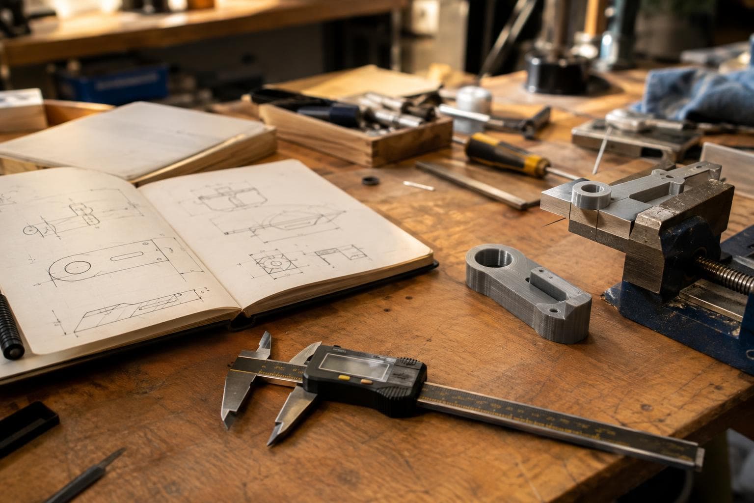
A straight plunge onto a finished edge leaves a visible mark at the entry point. The honest fix is not more sanding or a sharper cutter: change the toolpath so the cutter is already moving before it reaches the wall.
For a closed CNC profile, our default is an arc lead-in and a matching lead-out placed in waste. The arc lead-in is tangent to the profile, so the cut starts smoothly instead of forcing the tool into the finished wall at a direction change. The witness mark still exists, but it lands where the part will be discarded.
Why a straight plunge leaves a witness mark
A plunge puts the cutter under sudden radial and axial load at one coordinate. On a finished outside profile, that load can deflect the tool, compress wood fibres, rub plastic, or leave a small dwell mark while the spindle reaches its cutting load. Even if the machine holds position perfectly, the cutter is entering material at the edge rather than arriving along the cutting path.
The mark gets worse when:
- The cutter is ramping down while it touches the wall.
- The programmed feed is too slow for the material, creating a dwell.
- The cutter is dull, packed with chips, or too large for the machine's rigidity.
- The profile begins near a corner, where two walls increase engagement.
- The cut direction changes at the entry point.
- The toolpath starts at the same visible coordinate on every part.
A straight plunge can be acceptable inside a pocket when the plunge point will be removed by a later operation. It is a poor default for the final pass on a visible profile. Drilling a hole first does not cure the problem if the cutter still enters the finished wall at the same point.
Arc lead-ins change the geometry, not the cutter
A lead-in is spare toolpath before the profile begins. For an outside contour, the cutter center starts in the surrounding waste, follows an arc, and joins the offset profile. The arc lead-in is tangent to the profile at that join. The cutter is already at its programmed feed and has reached stable cutting engagement before it touches the part boundary.
That tangent condition matters. If the arc meets the profile at an angle, the entry is still a small directional impact. If it meets tangentially, the tool direction changes continuously through the join. In CAM, check the tool-center path rather than only the nominal drawing line. Cutter radius compensation and inside or outside offsets change where the physical cutter meets the material.
A useful starting point for wood and common machining plastics is a lead-in radius around 0.5 to 1.5 times the cutter diameter, with enough surrounding waste for the full arc. For a 6 mm cutter, that means a radius of roughly 3 to 9 mm. Smaller radii save space but make the direction change tighter; larger radii give the cutter more time to settle but may run into a nearby feature.
The radius is not a universal setting. Thin sheet, a flexible gantry, a long tool stickout, and brittle plastic all push toward a larger, gentler entry. A rigid machine cutting a thick board may have room for a smaller one. If the arc cannot fit, change the part geometry or move the entry to a larger waste area instead of forcing a decorative lead-in into the finished profile.
For most closed profiles, use a lead-out as well. It carries the cutter away from the profile before the machine stops or returns to the start point. Without one, the end of the contour can leave a second witness mark even if the entry was clean.
Pick the entry move for the material and the waste
The right CNC entry move is the one that protects the finished wall without creating a new problem elsewhere. These are the choices we use when setting up a final profile pass.
| Entry method | Motion at finished wall | Typical witness location | Main strength | Main failure mode |
|---|---|---|---|---|
| Straight plunge | Axial entry followed by an abrupt change to profile direction | Finished edge | Minimal XY clearance | Visible dwell, burr, or fibre breakout at one point |
| Tangent arc lead-in | Continuous XY motion into the offset profile | Waste beside the profile | Smooth engagement and controlled entry | Arc runs into a hole, pocket, clamp zone, or adjacent part |
| Linear lead-in | Straight motion into the profile, ideally tangent to its direction | Waste along a short line | Easy to fit and easy to inspect | An angled join can still mark the wall |
| Helical or ramped entry | Gradual Z descent while moving in XY | Waste area or a sacrificial interior | Reduces axial shock where a plunge is difficult | Extra clearance, longer path, and possible floor witness |
For a normal outside profile in plywood, hardwood, MDF, or machining plastic, we pick the tangent arc unless the sheet layout leaves no room. A linear lead-in is the fallback when the waste strip is narrow. A helix or ramp belongs in the waste when the material, tool diameter, or machine does not tolerate a direct plunge; it is not automatically better for a final edge.
Cut direction still matters. Climb and conventional milling change the direction of cutting force, chip evacuation, and edge breakout. On a rigid CNC router, climb cutting often gives a cleaner visible edge in wood, but backlash or a flexible setup can make the cutter pull into the work. Keep the lead-in on the same side of the contour as the chosen cutting direction, then verify the simulation and run a scrap test.
Size the lead-in from the cutter, not the drawing
A lead-in is part of the manufacturing geometry. It needs clearance from the finished part, tabs, clamps, screws, vacuum pods, neighbouring parts, and any pocket that is not waste. It also needs enough travel for the cutter to reach cutting speed without being asked to remove a full-width chip at the join.
Start with the cutter diameter and the available waste:
- Use a radius of about 0.5D to 1.5D for a first test, where D is the actual cutter diameter.
- Keep the arc entirely in waste, including the cutter's full radius, not just the tool centerline.
- Put the lead-in on a long, straight portion of the profile when possible.
- Keep the lead-in away from an outside corner by at least the radius of the cutter, and more if the material chips easily.
- Put the lead-out in the same waste region only if it cannot overlap the lead-in in a way that doubles engagement.
- If the profile has a visible face and a hidden face, place the join on the hidden face rather than relying on post-processing.
The lead-in does not compensate for a bad feed and speed. If the cutter is rubbing, the arc only moves the damage into a different location. For a new material, use a scrap panel with the same thickness, cutter, workholding, and tool stickout. Cut one straight edge with a lead-in, then inspect the join under the same light used for the finished part.
Most failures are visible in the toolpath preview if the preview is inspected as a manufacturing drawing rather than as a green line on a screen.
Check the physical cutter path
Display the cutter diameter or swept tool shape if the CAM system supports it. Confirm that the cutter, not just its centerline, stays in waste during the arc. Check the entry at the actual Z depth, since a pocket wall or stepped sheet can remove clearance that existed at the top view.
Check the feed transition
The tool should begin moving in XY before it touches the finished wall. Avoid a feed hold or programmed reduction directly at the tangent point unless the controller requires it. If a ramp is used, confirm that the cutter reaches the intended depth before the final profile begins, or that the remaining axial load is suitable for the material.
Check the end of the contour
A lead-out prevents the cutter from stopping on the finished wall, but it can create a gouge if it heads back across the part. Keep the exit in waste and make sure the next rapid move occurs only after the tool has cleared the material in Z or XY.
Check small features separately
A lead-in that works on a 100 mm outside curve may be impossible on a 12 mm tab or a narrow slot. Do not scale the same arc into every feature. For small internal profiles, a ramp in a removed area, a pre-drilled hole, or a sacrificial extension can be more reliable than an arc that changes the intended dimension.
A witness mark in the waste is acceptable. A witness mark on the part means the waste boundary was drawn too close, the toolpath was offset incorrectly, or the lead-in did not actually stay tangent.
When a layout has no waste, add deliberate sacrificial geometry if the design allows it. A dog-bone or small entry tab can move the mark out of the final boundary, but it changes cleanup and may affect fit.
For a visible edge with no room for a lead-in, leave the cleanest straight section for the entry and reserve the corner for later hand finishing only if the design permits it. Do not put the entry on a tight internal corner. The cutter is already dealing with changing engagement there, and the extra plunge load usually makes the defect more obvious.
A smaller cutter can create room for a smaller arc, but that trade is not free. It may require more passes, a lower feed, greater deflection control, or a longer machining time. Buying a smaller cutter is not the first fix for a layout that has not reserved waste. Move the entry, add sacrificial geometry, or alter the nesting first.
Frequently asked questions
Does a lead-in remove the witness mark completely?
No. It moves the witness mark into the waste and reduces the abrupt load at the finished wall. The entry can still leave a visible mark in scrap, and the profile can still show a defect if the cutter is dull, the toolpath is not tangent, or the machine deflects.
How long should a CNC lead-in be?
Size it from the cutter diameter and the available waste. A starting arc radius of roughly 0.5D to 1.5D is reasonable for many wood and plastic profile cuts, but the material, tool stickout, machine rigidity, and contour shape can move that range. Confirm it on scrap with the actual cutter and thickness.
Should the lead-out match the lead-in?
Usually, yes, if the profile is closed and there is enough waste. A matching tangent exit keeps the cutter from stopping on the wall. It does not have to be the same radius when space is limited, provided the exit remains in waste and clears the next motion.
The Boss Factory builds this kind of work to order through CNC & Precision Cutting, Custom Woodworking, and Design & Product Development; request it at /quote.
Related services
All services →Have a project in mind?
Tell us what you want built — we reply within 24–48 hours.